Infrared Body Sensing
Infrared sensing devices useful as gesture controllers for robotic musical instruments
by
dr.Godfried-Willem Raes
postdoctoral
researcher
Ghent University College & Logos Foundation
2007
This project describes a simple application of the combined use of three infrared PIR sensor devices for movement detection. The sensors are produced by Hygrosens Instruments Gmbh. The three sensors are used in combination with an ARM microprocessor (LPC2103) to produce a midi data stream.(1)
The project -nicknamed PIR2- is a further development of our earlier experiments with PIR sensing devices in the early nineties. In those years, after many experiments, we fully rejected the use of the available devices because of their very low reaction speed and extremely high noise levels. These properties made them prohibitive for musical gesture sensing applications where reliability and fast response are mandatory. Things have qualitatively improved over the years however, and so we decided to give this technology another chance in the realms of our musical and artistic applications.
In itself, infrared technology seems very promising if it comes to detecting moving live bodies since here we work with the radiation emitted by these bodies directly. Human bodies normally are at a temperature of 37 degrees Celsius (310.15 °K) and hence must radiate electromagnetic waves with a frequency spectrum showing a maximum at fm= w.T , according to Wien's law. In this relation w, derived from Wien's constant, equals 1.035E11 Hz/°K and T the absolute temperature of the radiating body. Thus, for a human body we come at a frequency maximum of 32THz corresponding to a wavelength of 9.368µm. The emission power, a normalized factor ranging from 0 to 1, equals unity only for a perfectly black body. This leads to the funny conclusion, that a sensing system based on body radiation works about twice as well for black people as compared to whites...(6) Obviously, this only applies when their bodies are not insulated from the environment with clothing. This frequency is in the very lowest part of the infrared spectrum. These frequencies are too low for detection by common infrared diodes, designed to operate somewhat below the visible spectrum of light, generally between 620nm and 950nm. Pyrodetectors, using a completely different technology mostly based on ferroelectric properties of triglycine sulfate (TGS), can detect this radiation range very well, showing sensitivities ranging from 7µm to 14 µm. The pyroelectric elements themselves are capacitive charge displacement devices and show off an extremely high impedance (ca. 100GOhm) and for this reason they are always produced directly coupled to the gate of a MOSFET. Due to this extremely high impedance, the sensing elements must show off a sensitivity inverse proportional to frequency. This means that it is inherently pretty slow, limiting frequency of input amplitude changes to below ca. 50Hz. In practice, the output signal is invariably low pass filtered to below this frequency, mostly to suppress the 50Hz mains frequency component. Note that typical output voltages for these sensors are below 450µV. (7) The problem in using these detectors for body sensing, is that the spectrum is obscured by many other low infrared sources in the environment, since emitted spectra are continuous and therefore objects at higher temperatures will also emit waves in the band we are interested in. Thus the received signal gives only a measure for the overall intensity of the radiation. For this reason, it would not suffice to place a very selective filter in front of the sensor. By using focussing optics, it is possible to measure temperatures on a small spot, as used in remote thermometers, but this does not help us for developing movement sensors. Rescue comes from another consideration: if the radiating bodies move, we can discriminate the emitted signals by placing a fine fresnel lens in front of a sensor composed of at least two sensing elements. This is the fundament behind the design of PIR sensors, reacting only to changes in the frequency range of interest. This also seems to entail that the differential signal amplitude should correspond to the distance between body and sensor, since the surface of a body remains pretty constant. The relation, in theory, follows a square law. It also appears that it should be easy to determine the precise angular position in space, given a suitable lens system. For the latter, in regular PIR devices, Fresnell lenses placed in front of the pyrodetector are invariably used. For good hemispherical sensing, the sensor should be internally composed of four elements. Angular speed seems derivable from the frequency of the output differential signal. The new PIR sensor we are examining here is the PIR STD (Order number CON-PIR-STD-172526), claiming a sensitivity up to 12 meter. After the data sheet, we get from the analog outputs a signal with a frequency between 0.2Hz and 10Hz, proportional to detected angular speed. The resolution is pretty low as it is determined by the optical characteristics -the number of bands- of the Fresnell lens used. In this case, the data sheet gives 11 bands horizontal with a spacing of 10 degrees and 5 bands vertical, with an unevenly distributed spacing of -30, -20, 0,+20 and +30 degrees. This signal is symmetrical around the halved power supply voltage, but the circuit provides in a second analog reference output used internally as Vc/2. This provision makes interfacing to a microcontroller pretty simple. The sensitivity angle is ca. 100 degrees, horizontal. In the vertical plane it is 60 degrees. A digital output is available as well, derived from a simple window comparator circuit in the sensor module. This output is meant as an alarm output, triggering on detection of body movement. The internal circuit for the sensor module (component values added by us after reverse engineering) is given below:
In our evaluation experiment, we used three sensor modules placed 60 degrees apart, such that the complete coverage becomes over 180 degrees, hemispherical and with a good mutual overlap. In the horizontal plane their individual sensitivity angle is -50 to + 50 degrees. So at the extreme opening angles we cover a range of 220 degrees. The angular sensitivity after the datasheet looks like:
We optimized the sensitivity for use with naked bodies in front of the sensors. In contrast to radar sensors (2), these devices have no backward lobes at all, which is an important advantage in stage- and theater applications. However, the dynamic range of the device is severy limited by the excessive noise generated in the sensor. Practical values will be below 28dB, and as a consequence a ADC resolution of 5 bits will be enough.
The circuit we designed looks like:
Everything fits nicely on a Eurocard format (100x160) prototyping board. The reference output from the PIR modules is very high impedance (ca. 100k) and therefore we connected it (with the three references in parallel) to the AD0 input pin via a 470k resistor. To suppress 50Hz interference, we added a low leakage 1µF capacitor. The disadvantage being that the sensor can only reliably be used after ca. 20 seconds of chargeup time. Buffering with a voltage follower opamp would have been a superior solution... The voltage dividers 5k1/10k on the analog outputs are to adapt the output range (0-5V) from the PIR modules to the input range of the AD inputs. In order to preserve 10 bit resolution, these resistors have to be 0.1% precision types. The ARM processor used for data acquisition and processing , the LPC2103, a 32 bit processor clocked at 60MHz, is mounted on one of the development boards produced by Corridium Corp. and forms a subsystem on our own board. It is shown in the picture below:
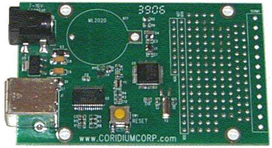
The timing resolution is 1µs, way above what we need here. The board can be programmed in Basic. The firmware for this board can be downloaded freely for examination: Arm_Midi_PIR2.bas. The data channel scan rate we found suitable is 25S/s. The data rate for our applications leads to a maximum of 175 midi messages per second (always corresponding to a sampling rate of 25 S/s per channel) but, when no movement is detected, can be as low as 25 midi messages a second. In order to reduce the inherent noise as much as possible, we do oversample the channels in the firmware each at 200S/s (8x oversampling), but the results are averaged and output only as 25S/s. By leaving out the pacing commands in the source code, the sampling and data rate can easily be driven up to ca. 250Scans/s leading to 1750 midi messages a second which is at the edge of what the midi protocol is capable of dealing with. If this is implemented, however, the receiving PC may get in trouble handling the midi data flow.
A procedure for the receiving end is part of our public domain GMT library g_lib.dll (source code module g_midi.inc) running on the Wintel platforms. (5) The Apple platform is not supported.
On the main board, there are DIP switches allowing the selection of the transmit midi channel, as well as for the selection of one of the maximum four programs in the firmware.
Programs available in the firmware are:
| bit 6 | bit 5 | bit 4 | bit 3 | ||
| 0 | 0 | 0 | - | analog | left PIR |
| 0 | 0 | 1 | - | analog | center PIR |
| 0 | 1 | 0 | - | analog | right PIR |
| 0 | 1 | 1 | - | count | left PIR |
| 1 | 0 | 0 | - | count | center PIR |
| 1 | 0 | 1 | - | count | right PIR |
| 1 | 1 | 1 | - | pulsetrain | all PIR's |
The processing board prototype, with power supply and all connectors-including the USB plug only required for programming-, looks like:
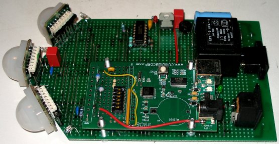 The blue
LED's were mounted between the PIR modules such that they give a visual indication
of the proper functioning of the sensors to the performers. Note also that the
sensors are placed upright on the PC board. To achieve this we used halves of
wire wrap IC sockets as connectors fitting the sensor modules Obviously, if
a proper PC board were designed, about half of the space would have been enough
to accommodate all the components. The prototype was mounted on a stainless
steel baseplate and chassis with a mounting thread for placement on a normal
microphone stand.
The blue
LED's were mounted between the PIR modules such that they give a visual indication
of the proper functioning of the sensors to the performers. Note also that the
sensors are placed upright on the PC board. To achieve this we used halves of
wire wrap IC sockets as connectors fitting the sensor modules Obviously, if
a proper PC board were designed, about half of the space would have been enough
to accommodate all the components. The prototype was mounted on a stainless
steel baseplate and chassis with a mounting thread for placement on a normal
microphone stand.
Evaluation:
To receive and process the data, we set up a structure containing
circular data buffers (10 seconds deep) for the three sampled analog channels,
as well as fields for the pulse-trains from the window comparators. After removing
the DC component from the analog data and rectifying and integrating we obtain
the amplitudes of the infrared radiation received. The distance was first calculated
by inverting the square root from the largest of these three values. (d =
1/ (SQR(maxvalue)). However, this did not lead to acceptable results. Thus
we plotted received amplitude versus distance and noticed that the amplitude
in fact goes down when the body comes closer than say 1 meter to the sensor.
The explanation being that for such distances, the fresnel bands may overlap
on the sensor and cancel out each other. So instead of using the theoretical
formula, we implemented a lookup table plotting amplitude versus distance. But,
since the implied curve is more or less a second degree equation, we can only
resolve distances unambiguously for distances in the far range where the curve
is not reversing.
The data obtained for distance under these restrictions came out to be pretty
reliable but in terms of precision, limited to about 5 bits over the range of
measurement (1.5 to 10 meter). It was possible to obtain information about the
angular position of the body detected, with a resolution of about 10 degrees
(4 bits). This was done by comparing the rectified and averaged amplitude values
from the three channels and calculating the angle using the differences.
Angular speed can be determined pretty well for slow movement speeds on the
condition that they take place at a reasonable distance from the sensor. At
higher speeds (say faster than 1m/s), or at very close proximity to the sensors,
the results become very shaky and unreliable. This speed was calculated by searching
for the last received full period in the pulse-train buffers and converting
into frequency based on the sampling rate interval of 40ms.
If the sensor were perfect and behaving linearly (quod non),
the traject (a) of a movement could be derived, using the rule of the cosine
for solving triangles, as follows:
a^2 = do^2 + d1^2
- 2d0d1,cos(10°), where
do and d1 are the distances as reported
on the rising edge of two received pulses after the look up table mentioned
earlier, but for the corresponding value for a one and the same sensor. The
speed of the movement then follows as v = a / t, where t is the time
between both rising edges. Unfortunately, this does not lead to useful data
in practice.
Over all, the sensor yields useful information but reacts slowly to dynamic
input. This slowness renders it unusable to retrieve information on the fine
motoric properties of expressive gesture. Thus it is certainly not an alternative
for our sonar- and radar based devices but it can be very useful to provide
complementary information or confirmative context.
Further investigations are planned. One of the major tracks to follow for improving both angular resolution and reaction time would be by using much finer rastered Fresnel lenses in front of the pyrosensor(s). The use of a very selective optical low infrared bandpass filter in front of the lens could also improve the signal to noise ratio, just as placing the sensor in a controlled temperature environment. On theoretical grounds, the use of fast CCD-based cameras with shutter speeds not lower than 500 fr/s and a sensitivity optimized for 10µm wavelengths (as far as we know, such devices are not on the market yet...) would offer a major breakthrough in this technology. In fact, we wonder why nobody seems to have thought of this. Probably because of the very unfortunate fact that most of electronic component research and production is guided by the dictates of horrible marketeers and inventors. These people focus on property and investment protection (hence the importance of intruder alarm systems!) rather than on the perspectives of analytical tools for movement and gesture analysis. A 'camera' built for dynamic pyrodetection would solve most of the problems related to the many attempts to use video camera information for gesture analysis. The most important feature being that such a camera would be only sensitive to moving bodies and would not give any information on the environment. Also, changing lighting conditions would not affect it. We would see only movements...(8)
Artistic applications
We are developing a series of studies and demonstrations to be performed with these sensing devices (often combined with many other more advanced sensors we have developed) , in which we try to explore different ways of mapping the sensor information (alone or in combination with either the sonar or radar version of our invisible instruments) on musical activity produced by our robot orchestra, composed of following robots:
Every time we finish a new robot
and add it to the M&M orchestra, we may add a new chapter in this suite
of pieces.
The sensor and signal conditioning circuit is available for any competent composer
wanting to develop a piece or performance using it. Since the use of the instruments
requires software to be written, it is highly advisable to study our <GMT>
software and its functionality with regard to this instrument. As an alternative,
the public domain language PD can be used as well. Useful PD patches are being
developed by our collaborators Kristof Lauwers and Johannes Taelman. They will
be available upon demand. This device can be used in combination with our PicRadar
sensors operating on 9.5GHz as well as with a set of Quadrada
sensors operating on 2.4GHz. Uses in combination with the
hybrid sensor using both sonar ranging and Doppler radar are possible as
well. The combination of these PIR sensing devices with the (non wireless) AXE3
acceleration devices is also very promising.
Other artistic applications:
Kristof Lauwers "¶ r^2", for robot orchestra and a nude dancer. Premiered on 19.12.2007 in the Logos Tetrahedron in Ghent.
Notes:
(1) This project is part of the ongoing research
of the author in gesture controlled devices over the last 30 years. Earlier
systems, based on Sonar, Radar, infrared pyrodetection, accelerometers and other
technologies are fully described in "Gesture
controlled virtual musical instrument" (1999), in "Quadrada"
(2003), "picradar" (2004) as well as in
his doctoral dissertation 'An Invisible Instrument' (1993). Artistic productions
and compositions using these interfaces and devices have been: <Standing
Waves>, <Holosound>, <A
Book of Moves>, <Virtual Jews Harp>, <Songbook>,
<Slow Sham
Rising>, <Gestrobo>, <Technofaustus>
, "PicRadar Studies" etc. The research is since 2005 supported in
part by the Ghent University College (Hogent), where I am employed as a post
doctoral researcher.
(2) Interfaces for gesture using radar technology are described in "Quadrada"
(Ghent, 2003)
(3) Detailed schematics for the ARM evaluation
board as well as programming manuals are available from http://www.coridiumcorp.com.
(4) People interested in buying the sensors as described here (fully functional, calibrated and including the programmed ARM processor) can take contact with the author. Cost, depending on the version required start at 1000€ for a triple transducer.
(5) The compiler used for the application code in <GMT> is Power Basic Windows Compiler V8.04. The URL is: http://www.powerbasic.com. The names of the functions in the library (source file g_midi.inc) relevant for this sensor are: GetPir2SensorPointer, PIR2_Input (), PIR2_Stop(). The complete <GMT> source code is available in the appropriate directory on our website.
(6) This only under the assumption that black people can effectively be considered more black than white people for the wavelengths we are talking about here, an assumption that needs to be proved by experiment. So, don't take it for granted.
(7) Cf.. datasheets for the RPW100, RPW101, RPW102, RPY100, RPY102, RPY107, RPY109, RPY222 devices in the Philips Semiconductor Sensors databook, volume SC17, 1989 edition.
(8) In our wildest
fantasies, it seems possible to design and fabricate a (sort of) CCD chip composed
of say 1000x1000 round pixels, each a little smaller than 10µm in size
such that each pixel could be tuned to resonate at the wavelength of 32THz.
Such a chip substrate, preferably in a triangular 60 degree arrangement, would
measure 1 square centimeter, and due to the small size of the pixels, respond
quickly.  The required
mosfets can, with available technology already be fabricated on chip. The read-out
logic could profit from already existing designs for CCD cameras. After we wrote
down this dream, we discovered that devices implementing this approach actually
do exist, but not only in as far as they can be bought by private persons or
institutions, are extremely expensive but also, they all fall in the domain
of military technology. Some relevant links: http://en.wikipedia.org/wiki/Thermographic_camera
as well as http://en.wikipedia.org/wiki/Night_vision_goggles. If you delve any
further you enter into military domains. Who takes up the challenge to produce
something more constructive?
The required
mosfets can, with available technology already be fabricated on chip. The read-out
logic could profit from already existing designs for CCD cameras. After we wrote
down this dream, we discovered that devices implementing this approach actually
do exist, but not only in as far as they can be bought by private persons or
institutions, are extremely expensive but also, they all fall in the domain
of military technology. Some relevant links: http://en.wikipedia.org/wiki/Thermographic_camera
as well as http://en.wikipedia.org/wiki/Night_vision_goggles. If you delve any
further you enter into military domains. Who takes up the challenge to produce
something more constructive?
Bibliographical references:
First published on the web: 10.11.2007 by dr.Godfried-Willem Raes
Last update:2010-10-02