<PicRadar>
a radar based gesture controlled instrument using MIDI
by
dr.Godfried-Willem Raes
post-doctoral
researcher
Ghent University College & Logos Foundation
2004
PicRadar is a microwave radar based installation for capturing information on human body movement to be used for controlling automated musical instruments and robots. The system consists of a set of radar sensors in the 9.35GHz band coupled to Microchip PIC controllers such that the interfaces output data using the midi protocol directly. Of course the equipment can be used as a controller for midi devices such as synthesizers or audio effect processors, as well as for real time audio processing. In these functions it contitutes a substantialy improved version of our earlier sonar based invisible instruments. With this setup, it is possible to retrieve absolute information about the 3-dimensional position of a player as well as about the size and aspect of the surface of the moving body. Also absolute movement velocity and acceleration can be derived as parameters, provided a multi-sensor system is used. The system is inherently wireless and as such it enables the realization of invisible instruments. It is proposed as an alternative for our <Quadrada> system, presented in 2003, for which specific data acquisition hardware (a National Instruments PCMCIA DAQ-card, or a USB-6210 device) was required.
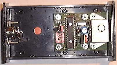
This article presents the hardware, comments on its design, the software implementation as well as it discusses some artistic applications. The equipment is available at the Logos Foundation in Ghent . It is open to composers, performers and scientists for experiment and development of productions. The ready to use sensors can also be ordered and bought from us. (2). The picture below gives you a view of the contents of the small prototype cabinet housing the circuitry.
Hardware
In the Logos research labs radar devices are being researched
operating in different frequency bands: 1.2GHz, 2.45Ghz, 9.35GHz, 10.5GHz, 12GHz,
22GHz. This report reflects our findings and realisations using the 9.35GHz
band.
The hardware side of this installation consists of the following electronic
components:
1. four microwave radar devices.
These make use of microwave sensors produced by Waldmann under typenumber HFMD10. Their operating frequency is specified at 9.35GHz. The microwave power is below 1mW. (5) The emitted electromagnetic waves from the patch antenna are reflected by reflective surfaces and if in movement, these will cause a Doppler shift between emitted and reflected signal. The HF mixer is inherent to the Gunn diode used in the patch antenna. The mixer is followed with a low frequency preamplifier and filter stage, outputting the Doppler differential signal directly. As to human bodies, the most reflective surface is the naked skin. We performed measurements showing that a pullover gives a damping in the order of at least 15dB, thus reducing the resolution of the interface effectively with a factor 6 or worse. Even a shiny T-shirt, reduces the amplitude of the reflections with 6dB. Hence our advise to always perform naked with this (and in fact, any doppler based) invisible instrument.
Doppler formula:
fd = 2 v fo / c
so, after solving the device specific constants we get:
fd = 62.3 v
This holds for movements in line with the axis of the sensor. For other angles, the formula becomes:
fd = 62.3 v cos(a)
Where a is the angle between the movement and the axis of the sensor.
The specified range for this device is limited to the frequency band 2Hz - 750Hz. The highest value would correspond to a movement velocity of 12 m/s, which is impossibile for a human body to reach. The practical upper range for humans is limited to 5m/s corresponding to a doppler frequency of 311Hz. Inherent noise from the transducer is ca. 20mVpp. Maximum output voltage from the transducer is 2.5V. The signal noise ratio hence is 42dB. Thus, we have to sample the signal at 620 S/s minimum, conforming to the Nyquist theorem and a sampling resolution of 10 bits is adequate.
Signal amplitudes are inverse proportional to the square of the distance to the antenna and directly proportional to the size of the surface of the moving body. (6) The detection range for these devices is limited to 5 – 7meters, somewhat smaller than in case of the quadrada setup. Noise limits the range of the unit. Since we want the device to operate in real time, there is no way to resolve signals below or around the inherent noise level of the devices. The polar sensitivity, according the the datasheet, shows an opening angle of 60° (within -3dB). The polar diagram below conforms to our measurements in july 2004.
Note that the device is not insensitive to movements to the sides and even to the backside. The diagram shows clearly a lobe on the back. The measurements were performed with non enclosed devices and no metal parts in the immediate neigbourhood.
In our setup we use four circuits as described above, each set to a different MIDI-channel. Since the bandwidth for each device is only ca. 1000Hz, there is only a minimal chance that two of these circuits would happen to operate on a frequency less different than this bandwidth. In case this would be the case - Murphy being the way he is, this will happen on a crucial day or occasion- the setup will prove to be completely unworkable. You should select a different set of transducers, or play around a bit with the supply voltage, since operating frequency is to a certain extend a function of this parameter. (Do not go beyond the safe margins however: 8V to 15V for a frequency range of 9.30GHz to 9.40GHz). If you have equipment at hand, allowing precise measurement (within 0.01%) of frequencies into the GHz range, you should tune the radar modules such that they are at least 20kHz apart, thus avoiding all sorts of artifacts in the audio band.
The assembled production PC board of this sensor is shown on the picture below:
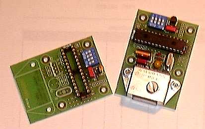
The DIP switch allows users to set the midi send
channel. The table below clarifies the different channel settings: 
2. Adapter board to connect the outputs from these 4 devices to 4 port midi interface connected to the (laptop) computer. This board also houses a linear stabilized power supply for the transducers. These require 15V dc and draw about 50mA each. This brings the total power requirements, including some safety margin to 15V/ 250mA, or no more than 4Watt. Standard 5pole 180° DIN connector cabling is used for the interconnections.
As an alternative, we also have a midi device available to merge the data from up to four radar devices into a single midi output. This is a modified box made by Midi Solutions and sold under the name Quadra Merge. In our modification, all pin 1's on the midi input and the midi out DIN connectors cary the positive pole of the 15V power supply. Pin 2 is connected to ground. The 15V power supply must be connected to the coaxial plug socket mounted on the side of the box.
As we noted in earlier publications based on our research into microwave radar devices (1), the sensors used here can also be disturbed by ionising sources in their neighbourhood and range of sight. When using the 9 to 30GHz range, the effects of gasdischarge lights often makes the use of the equipment problematic. So the use of this equipment together with CRT's, TV-sets, TL-light, mercury vapor bulbs, our own digital loudspeakers, welding equipment, sodium vapor bulbs within a range of 10 meters around the setup should be discouraged.
Software
The software consists of two levels: a first level, encoded in the PIC microcontroller. This code samples the signals from the transducers at the required sampling rate and processes this data such that we get access to following parameters:
The sensors output their data at a rate of ca. 200 bytes/s. The second level is part of our <GMT> programming environment. Here the data from the four interfaces are combined in an attempt to make sense and gain relevant information with regard to gesture input.
The relevant procedures, including many more features than we can describe here, are integrated in our DLL library g_lib.dll. The source code -the relevant procedures are in the g_lib.bas and g_midi.inc, is available. The required exported functions are:
GetPicRadarPointer (devicenumber) AS DWORD
this returns a pointer to the structure defined for each transducer. This structure behaves like an object and sets and returns all relevant data, operational mode and parameters. Devices are numbered 0 to 3.
The derivation of meaningful information with regard to the gesture input is based on the same considerations and gesture typology as described in "Gesture controlled virtual musical instrument" (1999), with this difference, that the setup of the transducers in the form of a tetrahedron is not mandatory here. Of course, for the math involved to work well, one has to stick to the setup requirements and conditions implemented in the software.(4) The first set of studies developed so far, uses a diagonal cross setup (square) , since this makes determination of position in space pretty straightforward:
Let Ar1,Ar2,Ar3,Ar4 be the signal amplitude of the output of the sensors, fr1, fr2, fr3, fr4 the frequencies of the signals, S the surface of the moving body (for ease of calculation, we consider it is a sphere, seen as a circle by all sensors), k a scaling factor, L1, L2, L3, L4 the distances to the sensors. Then, in the setup as above we have:
Ar1 = k. S / (L1+1) ^ 2 and Ar3 = k.S/ (L3+1) ^ 2
as well as
Ar2 = k.S / (L2+1) ^ 2 and Ar4 - k.S / (L4+1) ^ 2
Thus we can write Ar1 / Ar3 = (L3+1)^2 / (L1+1)^2 as well as Ar2/ Ar4 = (L4+1)^2 / (L2+1)^2, so meaning that it is possible the locate the movement regardless the surface of the moving body parts. Of course the condition that there must be movement, holds. If we normalize the distance between opposite sensors (L1 + L3 = 1) , and state Q = SQR(Ar1 / Ar3) we simply get:
L1 = (2 - Q) / (Q + 1) and L3 = (2Q - 1) / (Q + 1)
Depending on the values of Ar1 and Ar3, it follows that the range for L1 and L3 becomes -1 to 2, meaning that we can also resolve positions beyond the space between both sensors. However, for our calculations we will limit the range to the traject 0-1. The size of the moving surface, as seen by the radar couple 1-3, can now also be derived as:
S1,3 = (Ar1.(L1+1)^2) = (Ar3.(L3+1)^2)
In practical measurement this equality will never be exact, but we can take advantage of this redundancy by increasing the certainty and calculating an average value for S as:
S1,3 = ((Ar1.(L1+1)^2) + (Ar3.(L3+1)^2)) / 2
The other pair of radars, 2-4, will similarly lead to the derivation of a value for S. Depending on the orientation of the moving body, this value will be different. The proportion between both values allows us to derive the orientation of the body within the square coordinates. Thus some information with regard to the shape of the moving body can be retrieved as well: the values of the size of the moving surface as seen by the radars 1 and 3 , and these seen by radars 2 and 4 will depend on the orientation of the moving body in the space: Since front and backside of a human body show more or less a twofold surface as compared to its sides, we can estimate the orientation or aspect of the moving body using this equation:
S1,3 / S2,4 = ((Ar1(L1+1)^2) + (Ar3(L3+1)^2)) / ((Ar2(L2+1)^2) + (Ar4(L4+1)^2))
Note that position determination as well as surface determination is also independent of movement velocity. This velocity however is also a function of the cosine of the movement angle. But, since we can calculate the position as shown above, it is now also possible to derive the absolute movement velocity. Moreover, we can do it with a lot of detail: in order to estimate the global velocity of the moving body, we can use the positional information against time: this works particularly well for very slow movements. For fast movements, we can use the available spectrum analysis with the cosine correction and retrieve information also about the spectral characteristics of the gesture waves (fluent, disruptive...).
Once we know L1, L2, L3 and L4, we can find the coordinates from the center of the setup (defined as point 0,0) as follows:
After conversion to polar coordinates, we get vector magnitude and angle. To derive the angle of movement we need to know two points on the traject of the movement:
ppc.real and ppc.imag for the previous point and pc.real = xpos and pc.imag = ypos the a more recent point. We now shift the line connecting these points (the movement traject) to the center of the coordinate system:
After conversion to polar, we now get p.mag and p.ang, and the cosine of p.ang is the factor by which we have to divide the frequency of the vector signal in order to get the absolute speed of the movement in the traject. At least, for the even (0 and 2) numbered transducers. For the odd ones (1 and 3) we can use the sine of the same angle. So:
This way the values returned in our structure , in the .vf field, are obtained. Since there is a fourfold redundancy, the found values can be averaged to reduce noise and inherent movement uncertainty. (5) If the signal amplitudes are high enough above the noise level, we can also derive relevant information with regard to the change of shape in time of the moving body. This can be very significant for dance movement analysis.
For a tetrahedral setup, the math involved is different and more complicated but pretty straigthforward as well. It has the advantage that we can derive full 3-dimensional positional information. Moreover, the uncertainty of the resulting values is much lower in this setup, since the angles all are one third smaller.
The data acquisition card we used during development had 12 bit resolution. Since the normal noise level of the system is around 4, we should consider the last 2 bits as irrelevant. The practical resolution, and therefore the precision of the system, cannot be better than 10 bits. There is absolutely no advantage in using a higher resolution data acquisition card for this application. At least, unless lower noise or higher power microwave devices become available... For this reason we could use a Microchip PIC controller with analog inputs with 10 bit resolution for the final and production version. The firmware for this PIC microcontroller is capable of outputting the data as a midi stream directly.
As a tool for evaluation, research and setup, we programmed a radar-display in GMT. The horizontal axis (line A-C) corresponds to the Radars 1 and 3, the vertical B-D, to 2 and 4. A blue ellipse is shown on the screen on the place where movement is detected. The size and aspect ratio of this ellipse is in proportion to the size and orientation of the moving body. The red polygon under or sticking out from the blue circle, gives an estimate of the certainty margins. Ideally, there should be no red visible for precize positional detection.
This radar screen is updated 16 times a second, so fast enough for a good video-like appearance.
Artistic applications
The <PicRadar> suite is a collection of studies for a naked performer (some studies use up to four performers), in which we tried to explore different ways of mapping gesture information on musical activity produced by our robot orchestra, composed of following robots:
Everytime we finish a new
robot and add it to the M&M orchestra, we add a new chapter in this suite
of pieces.
The equipment is available for any competent composer wanting to develop a piece
or performance using it. Since the use of the instruments requires software
to be written, it is highly advisible to study our <GMT> software and
its functionality with regard to this instrument. As an alternative, the public
domain language PD can be used as well. Usefull PD patches have been developed
by our collaborators Kristof Lauwers, Hans Roels, Yvan Vander Sanden, Lara Van
Wynsberghe and Johannes Taelman. They are available upon demand.
Dr. Godfried-Willem Raes
![]() click
here to see a video of a performance of the PicRadar studies by the author
click
here to see a video of a performance of the PicRadar studies by the author
Notes:
(1) This project is part of the ongoing research of the author in gesture controlled devices over the last 40 years. Earlier systems, based on Sonar, Radar, infrared pyrodetection and other technologies are fully described in "Gesture controlled virtual musical instrument" (1999), in "Quadrada" (2003), as well as in his doctoral dissertation 'An Invisible Instrument' (1993). Artistic productions and compositions using these interfaces and devices have been: <Standing Waves>, <Holosound>, <A Book of Moves>, <Virtual Jews Harp>, <Songbook>, <Slow Sham Rising>, <Gestrobo>, <Technofaustus> etc.
(2) People interested in buying the sensors as described here (fully functional and inclusing the programmed PIC) can take contact with the author. Cost, depending on the version required start at 350€ for a single transducer. A complete system, consisting of 4 sensors, a powering box and power supply costs ca.1500€ Update information 02.08.2009: The sensors we used here are no longer produced thus we can no longer take orders neither. Alternatives are available requiring minor design changes.
(3) Microcode for the PIC in this project was written by Johannes Taelman. New versions have firmware written by Godfried-Willem Raes.
(4) A limitation of the square setup described here is that we basically retrieve all information in a plane. We have, unless a tetrahedral setup is used, no information with regard to possible vertical movement. Not that the square setup would be insensitive to vertical movement, since the sensitivity as follows from the polar diagram is hemispherical, but the information we retrieve is related to the projection of the movement on the plane connecting the four sensors. Future experiments will be performed using either a single suspended transducer or a cube using 8 transducers. Tetrahedral setups using 4 transducers, identical to the setup used for our sonar based invisible instruments, have been tested extensively as well.
(5) This is 30 times below the power of any normal wireless network transmitter (30mW) , and thus should be considered completely safe. In particular, taking into account that these devices are intended to be used on a distance and not close to the body.
Bibliographical references:
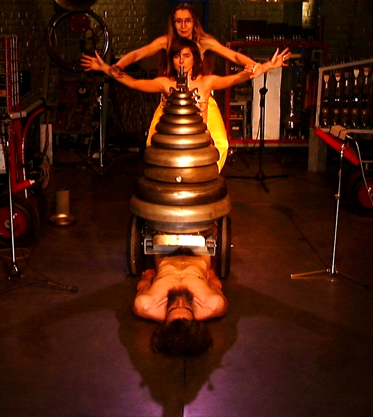
[Nicoletta Brachini, Moniek Darge and Godfried-Willem Raes in 'Views on the stuppa' by Kristof Lauwers and Moniek Darge, using the Picrada interfaces for playing our <Llor> robot. Gent, 2004].
The PicRadar devices were used also for the M&M streettheater performances in Brugges Corpus05, may 7th 2005, thoughout many <M&M> concerts in the Logos Tetrahedron and at the November Music Festival in Den Bosch, november 2006.
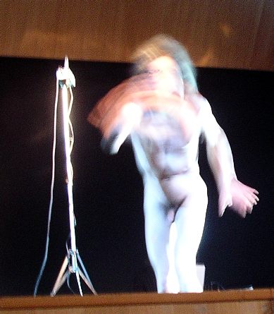
Godfried-Willem Raes performing <Sires Pic> in Denia, Spain, december 2005.
14th of july: premiere of 'Simb'AsPic" for the simba robot and Picradar interfaces. Ghent Feasts: Baudelopark, Spiegeltent, Trefpunt.
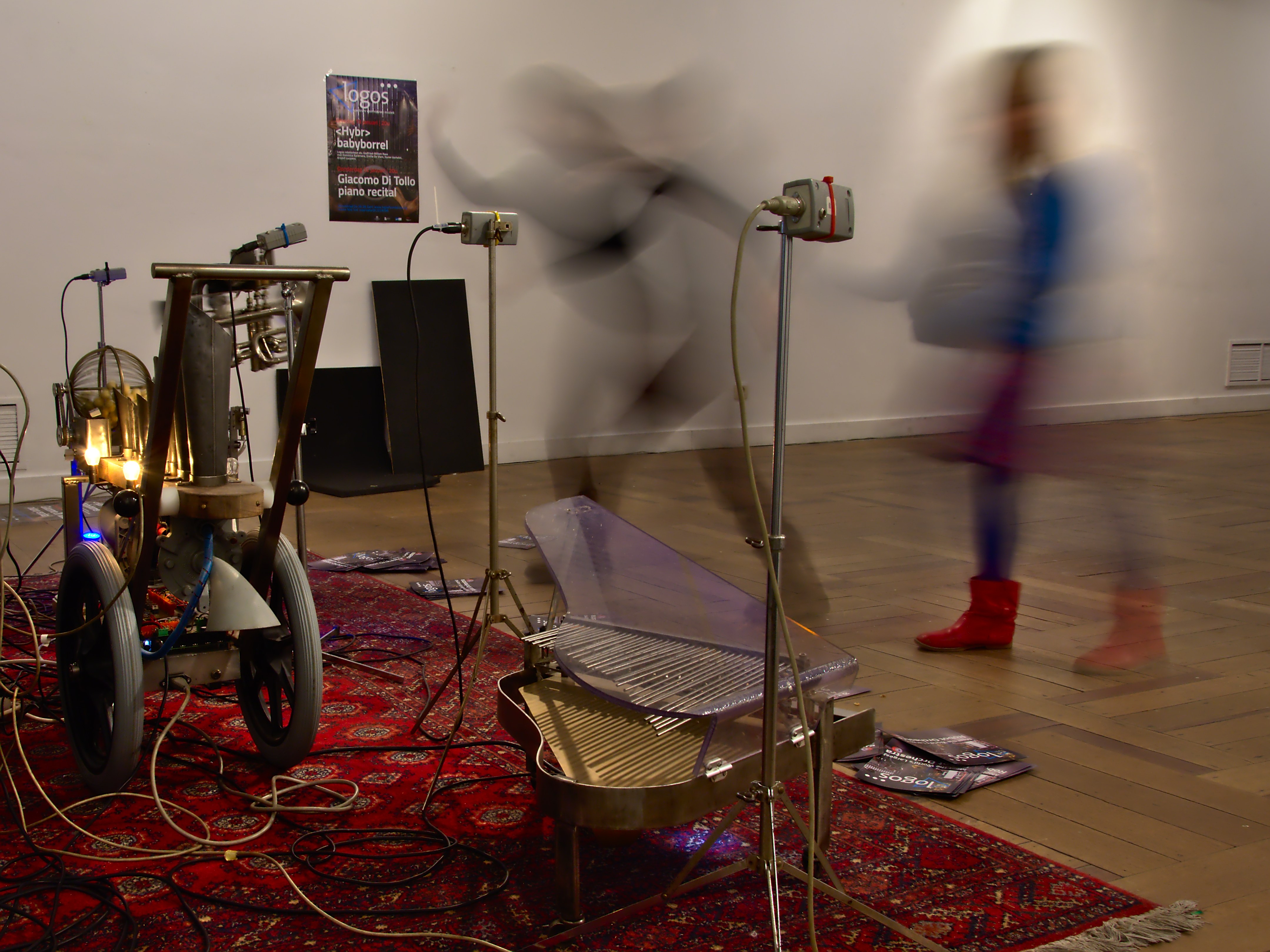
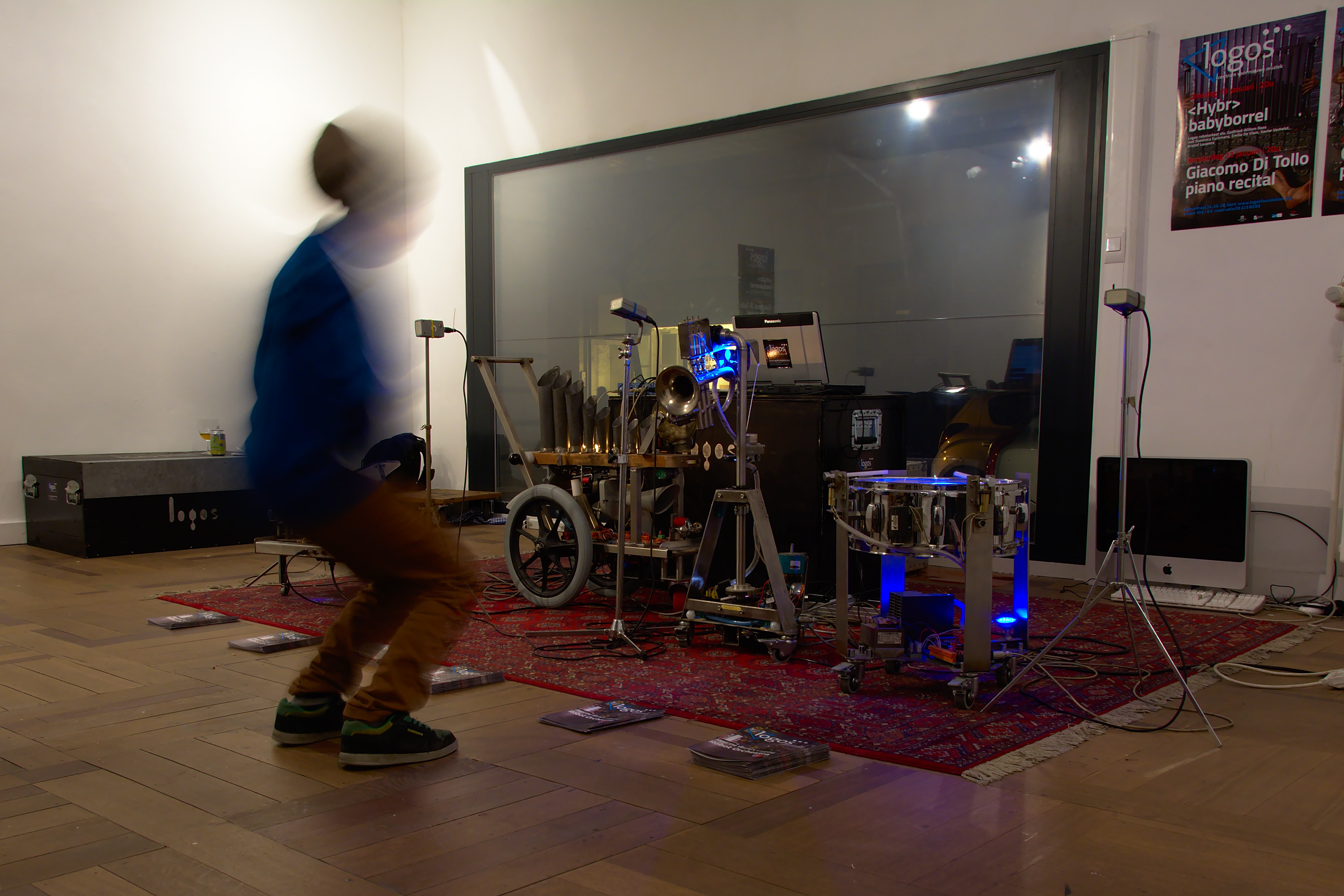
These devices are regularly in use in our installations for children with the small robot orchestra, as demonstrated in the pictures below:
First published on the web: 11.05.2004 by dr.Godfried-Willem Raes
Last update:2023-09-03