Acceleration Sensing
devices for acceleration sensing usefull as gesture controllers for robotic musical instruments
by
dr.Godfried-Willem Raes
post-doctoral
researcher
Ghent University College & Logos Foundation
2007
This project describes a simple application of the two dimensional accelerometer chips ADXL202, produced by Analog Devices, in combination with an ARM microprocessor (LPC2103) to produce a midi data stream.(1)
The project -nicknamed Axe3- is a further development of our 'Egg' (2) realized in 1995 for the control of one of our first player pianos. At that time the most sensitive solid state acceleration sensor available in chip form was the single axis ADXL50, with a sensitivity of only -50 to +50g. Later on, the ADXL05 (with a tenfold improvement in sensitivity) became available and we upgraded the design. In these first designs we used 3 chips to be held in a single hand, with the sensors alligned on x,y and z axis. The sensors used now have 2 axis of sensitivity (x, y) and a sensitivity of +/- 2g. The data output is available either as a couple of pulse width modulated signals, or as analog voltages. In this design we implemented two sensors, such that a performer can hold one in each hand. Mounting on the legs is obviously also possible. Each accelerometer is connected to the processing board by a thin cable ending in a standard keyboard type 6 pole mini DIN plug. These were actually recycled from old PC keyboards. The sensors can be easily attached to (boxing) gloves for ease of manipulation. They are mounted inside the shells of hollowed out male 3-prong Euroconnectors, providing a good strain relief for the cable.
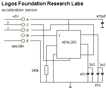
The value for the 240k resistor was selected such as to obtain
a 1.92ms period (T2) for the output signal. When using a timer with 1µs
resolution, this results in counter output values for the T1 pulse that will
never exceed 2047. The theoretical range for this sensor now becomes 512 to
1536, so wen we subtract the offset value (ca. 512), the returned values can
be expressed in a 10 bit number. However, the devices require precise callibration,
since their offsets as well as scaling factors can vary greatly from device
to device as well as from axis to axis. Fortunately, these errors remain pretty
much constant for a given device. Hence it is possible to compensatie in the
firmware using a device specific data set. Herewith we give the measured results
(in microseconds for the T1 pulse duration) for the devices we obtained:
| ADXL202 table | -2g value | -1g value | 0g value | +1g value | +2g value | offset for 0g=512 | scaling error |
| Right hand sensor X | 569 | 819 | 1069 | 1320 | 1569 | -557 | -2% |
| Right hand sensor Y | 689 | 927 | 1174 | 1412 | 1659 | -662 | -5% |
| Left hand sensor X | 408 | 647 | 885 | 1124 | 1362 | -373 | -7% |
| Left hand sensor Y | 551 | 791 | 1031 | 1271 | 1512 | -519 | -6% |
With the capacitor values fitted (49.2nF) the bandwith of the sensor is limited to 100Hz. Noise rms value of the output signal corresponds to 6.1mg, or 24.2mg pp. These values are only a bit larger then the resolution of the timers allow, since this resolution now is 4mg. The circuitry for the processing board is:
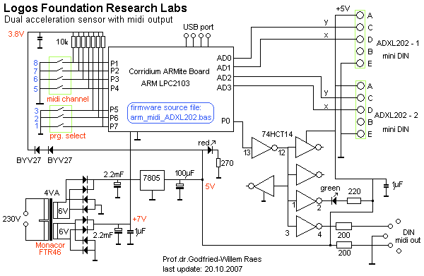
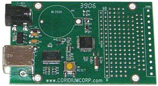
The ARM processor used, the LPC2103, a 32 bit processor clocked at 60MHz, is mounted on one of the development boards produced by Corridium Corp. It is shown in the picture below:
The timing resolution is 1µs -crucial in this application where we have to measure pulse widths. The board can be programmed in Basic. The firmware for this board can be downloaded freely for examination. Note that offset correction is embedded in the firmware, such that the output value 512 always correcponds to 0g. Scaling however, ought to be performed at the receiving side of the data since that can better be handled using floating point. Filename: Arm_Midi_ADXL202.bas. The data rate for our applications is limited intentionally to 128 midi messages per second, but by leaving out the pacing commands in the source code, can easily be driven up to ca. 400 messages a second, equivalent to a per channel sampling rate of 100S/s. If this is implemented, however, the receiving PC may get in trouble handling the midi data flow.
A procedure for the receiving end is part of our public domain GMT library g_lib.dll (source code module g_midi.inc) running on the Wintel platforms. (5)
On the main board, there are DIP switches allowing the selection of the transmit midi channel, as well as for the selection of one of the maximum seven programs in the firmware.
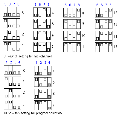
Programs available in the firmware are:
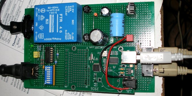
The processing board prototype, with all wires -including the USB plug only required for programming- connected, looks like:
It is perfectly possible to derive very precize rhytm information from appropriate gestural input and thus,we may conclude that these devices are perfectly suitable for the implementation of virtual conductors and similar applications. However the conversion of the acquired data to a reliable musical tempo took us many hours of software research. (6) For many applications where the sensors are used to control musical parameters, it came out that the conversion of the data obtained for the x and y vectors to polar coordinates, is often a very good idea. For instance if vector magnitude is mapped on velocity and angle on pitch.
Artistic applications
We are develloping a series of studies and demonstrations to be performed with these sensing devices mounted on gloves or on the legs, in which we try to explore different ways of mapping the sensor information (alone or in combination with either the sonar or radar version of our invisible instruments) on musical activity produced by our robot orchestra, composed of following robots:
Everytime we finish a new robot and
add it to the M&M orchestra, we may add a new chapter in this suite of pieces.
The sensor and signal conditioning circuit is available for any competent composer
wanting to develop a piece or performance using it. Since the use of the instruments
requires software to be written, it is highly advisible to study our <GMT>
software and its functionality with regard to this instrument. As an alternative,
the public domain language PD can be used as well. Usefull PD patches are being
developed by our collaborators Kristof Lauwers and Johannes Taelman. They will
be available upon demand. This device can be used in combination with our PicRadar
sensors operating on 9.5GHz as well as with a set of Quadrada
sensors operating on 2.4GHz. Uses in combination with the
hybrid sensor using both sonar ranging and doppler radar are possible as
well.
Notes:
(1) This project is part of the ongoing research
of the author in gesture controlled devices over the last 30 years. Earlier
systems, based on Sonar, Radar, infrared pyrodetection, accelerometers and other
technologies are fully described in "Gesture
controlled virtual musical instrument" (1999), in "Quadrada"
(2003), "picradar" (2004) as well as in
his doctoral dissertation 'An Invisible Instrument' (1993). Artistic productions
and compositions using these interfaces and devices have been: <Standing
Waves>, <Holosound>, <A
Book of Moves>, <Virtual Jews Harp>, <Songbook>,
<Slow Sham
Rising>, <Gestrobo>, <Technofaustus>
, "PicRadar Studies" etc. The research is since 2005 supported in
part by the Ghent University College (Hogent), where I am employed as a post
doctoral researcher.
(2) Cfr. article in dutch: 'Godfrieds Ei', Ghent 1995. An introduction to musical applications for acceleration sensors can also be found in our syllabus on experimental music composition at 2150.html
(3) Detailed schematics for the ARM evaluation
board as well as programming manuals are available from http://www.coridiumcorp.com.
(4) People interested in buying the sensors as described here (fully functional, callibrated and including the programmed PIC or ARM processor) can take contact with the author. Cost, depending on the version required start at 1000€ for a dual transducer.
(5) The compiler used for the application code in <GMT> is Power Basic Windows Compiler V8.04. The URL is: http://www.powerbasic.com.
(6) Parts of this tempo extraction research was done in collaboration with Kristof Lauwers.
Bibliographical references:
First published on the web: 20.10.2007 by dr.Godfried-Willem Raes
Last update:2010-03-31