Musical
Robot
Research project on
the development of new tools for musical expression
|
|
<Zip>
a robotic spring player
dr.Godfried-Willem
RAES
2009-2026
|
This robotic instrument has a very long history, as its first construction
was started in 2009 and only in 2026, it reached the stage of finalization.
On the way to its realization it had known very different appearances. It started
off as an attempt to create an automated quanun, but all our attempts to turn
it into a useful instrument failed. The main reason for the failing being the
too close spacing of the strings. No matter what kind of plucking mechanism
we imagined, it either took too much physical space (using bi-directional solenoids)
or it would be way too slow and monophonic (using a sledge mechanism with a
single plectrum) to allow automation of all of them. So the idea was dropped
for many years.
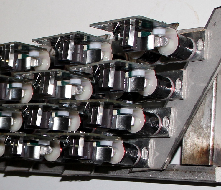
A first version made use of pluckers using bi-directional solenoids, in this
case solenoid assemblies made by Syndyne:
: These components
are normally used as register knobs on pipe organs with electromagnetic registration.
We contacted the factory in order to obtain these components with a straight
anchor, as this would be much easier to attach the plectra.
These components
are normally used as register knobs on pipe organs with electromagnetic registration.
We contacted the factory in order to obtain these components with a straight
anchor, as this would be much easier to attach the plectra. 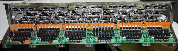 The picture shows the plucker mechanism with associated electronics before wiring.
However, we never got this mechanism to work well as a string plucker. Later
we found a good use for this mechanism in our <Tinti>
robot.
The picture shows the plucker mechanism with associated electronics before wiring.
However, we never got this mechanism to work well as a string plucker. Later
we found a good use for this mechanism in our <Tinti>
robot.
For many years we gave up altogether developing a plucked string instrument
until we decided to design a second prototype. This time using longitudinal
bi-directional solenoids with permanent magnets. These solenoids are stable
in either of their end positions and they only require a pulse of changing polarity
to make them change position. As this type of solenoid could not be obtained
with an anti-rotation shaft, we decided to design round plectra with a 2 mm
central hole for plucking the strings. The plectra were mounted on the shafts
with two stainless steel M2 nuts.
Not only the plucker assembly had to be completely build again and redesigned,
but also the electronics, including the power supply. This type of solenoid
requires pulses of alternating polarity, thus requiring H-bridges to drive them.
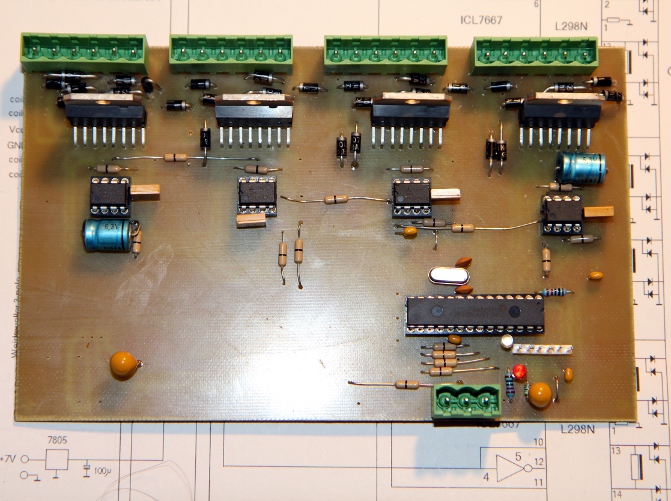
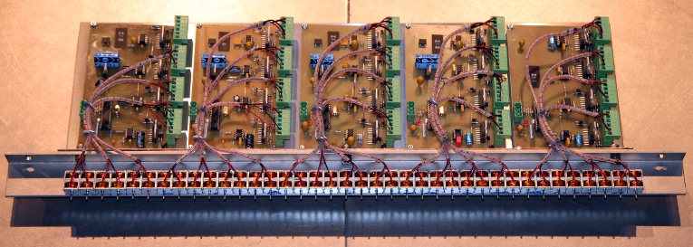
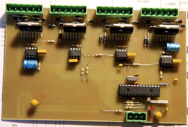
We used an old and proven H-bridge in IC form, the L298N. With a single 18F2525
microprocessor chip, we can steer a group of 8 solenoids. Here is the circuit:
 Five
of these boards were required for the complete qanun. The power requirements
turned out to be a lot more relaxed as compared to the first prototype design.
This mainly because of the pulse-only operation of the solenoids. However, these
solenoids having a DC resistance of only 4.2 Ohms, draw a pulse current of 2.8A
each, which is at the limit of what the L298 drivers can cope with. The data
sheet specifies a maximum of 3A, non repetitive pulse. The pulses being limited
to maximum 50ms with a 50% duty cycle relaxes the limits though. Unfortunately
there is as yet no integrated MOSFET H-bridge on the market with a wider range.
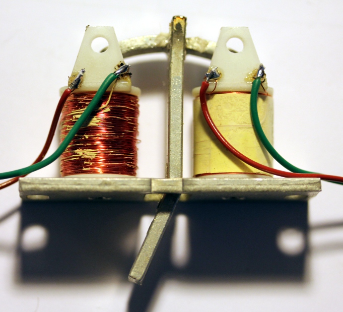
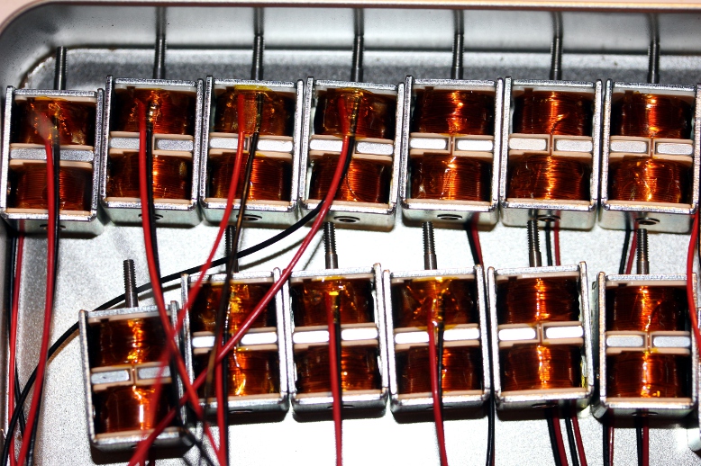
As to the power supply, a 12V / 500VA transformer and some unortodoxically paralleled
LT1024-12V regulators seemed adequate. Here is a picture of these small solenoids:
Five
of these boards were required for the complete qanun. The power requirements
turned out to be a lot more relaxed as compared to the first prototype design.
This mainly because of the pulse-only operation of the solenoids. However, these
solenoids having a DC resistance of only 4.2 Ohms, draw a pulse current of 2.8A
each, which is at the limit of what the L298 drivers can cope with. The data
sheet specifies a maximum of 3A, non repetitive pulse. The pulses being limited
to maximum 50ms with a 50% duty cycle relaxes the limits though. Unfortunately
there is as yet no integrated MOSFET H-bridge on the market with a wider range.
As to the power supply, a 12V / 500VA transformer and some unortodoxically paralleled
LT1024-12V regulators seemed adequate. Here is a picture of these small solenoids:
 Here is the circuit for the
power supply components:
Here is the circuit for the
power supply components: 
But, once more this mechanism was a complete failure when it came to plucking
strings. The solenoids just did not develop enough force in the mid position
of their trajectory, no matter how we tried to drive them. Thus we were forced
to drop the entire project once more.
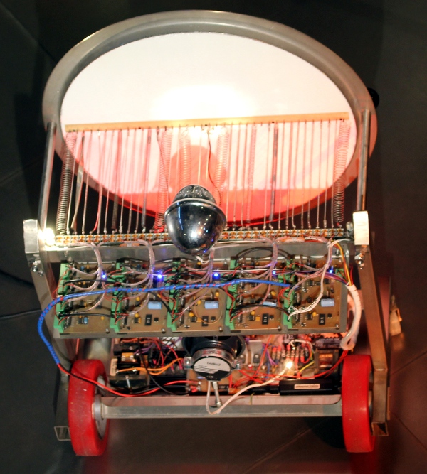
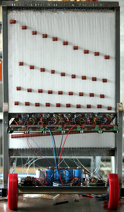
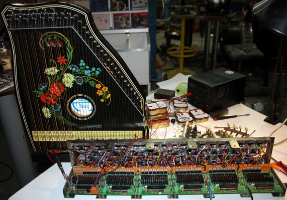
Many years later, in 2026, we turned back to the failed project with an entirely
different idea, dropping the plucked strings altogether. Now the new idea was
to use the bistable solenoids to drive springs in longitudinal resonance. The
solenoids having only very limited force (<=6 N, after the datasheet) , we
had to use quite weak springs, wound with pretty thin steelwire. The diameter
of the springs was limited by the distance between the solenoid anchors (ca.
13 mm) . As a resonator we used a circular piece of Styrofoam, thickness 30
mm, in a round stainless steel frame. Styrofoam was proven to be very efficient
as a soundboard and resonator in previous robots such as <Rodo>.
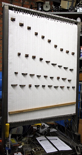
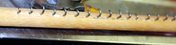
We constructed a wooden comb with 38 hooks on which we attached the springs.
This comb is clamped on the styrofoam board.
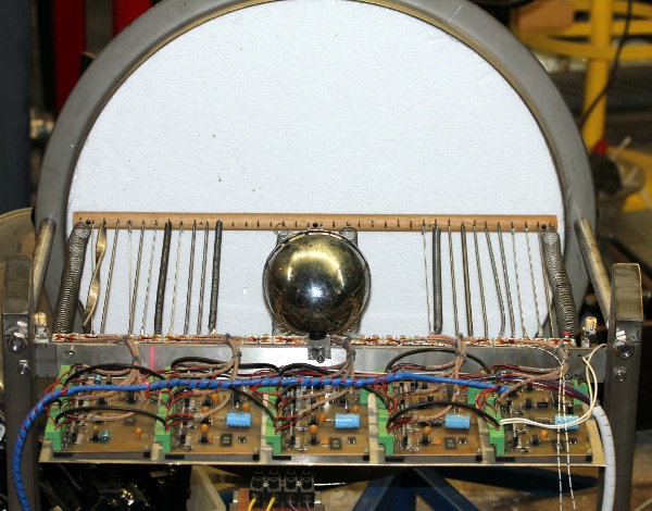
As the sounds produced by this mechanism appeared to be pretty soft in volume,
we decided to provide in some amplification. To achieve this we mounted a piezo
disk between comb and styrofoam resonator. The amplifier circuitry uses a vactrol
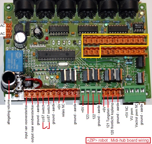
allowing control of amplification amount:  For
users, this is mapped on midi-controller #7, the standard volume controller.
Also this mechanism allowed us to implement tremolo effects on this robot. Midi
controller #5 sets modulation depth and #6 sets the modulation speed. In order
to minimize hum and noise, the entire audio system can be disabled with controller
#67. This switches the 19V power supply for the audio circuits on or off.
For
users, this is mapped on midi-controller #7, the standard volume controller.
Also this mechanism allowed us to implement tremolo effects on this robot. Midi
controller #5 sets modulation depth and #6 sets the modulation speed. In order
to minimize hum and noise, the entire audio system can be disabled with controller
#67. This switches the 19V power supply for the audio circuits on or off.
Only when integrated in the context of our robot
orchestra with its wealth of varied sensor systems allowing full interactivity
with gesture and audio, this automate will become a true robot. That's after
all were its destination is to be sought.
Midi Mapping and implementation:
Midi channel: fixed to 4 (counting 0-15).
Note Off: Implemented for all notes in the range. Note Off does not reset the
repetition rate.
Note On: Implemented for notes in the range. Velo-byte is used for the striking
force. The range is rather limited. The lights are also mapped on notes, but
make use of a range outside the normal range of the instrument.They are mapped
on notes 120 (frontal light) ,121 (tungsten light on the base), 122 and 123
(bright red LED's left and right), 124 (Halogen bulb underneath). The velocity
byte steers the flashing speed. With value 127, the lights stay fully on.
Key pressure: can be used to let notes repeat automatically. The pressure value
sets the repeat frequency. The command can be sent even prior to note-on commands.
The value send will be preserved until reset with a key pressure command for
the corresponding note with value zero. Controller 30 will override individual
key pressure commands.r 14: Sets the minimum velocity
level required to pluck the string. The setting for this controller has to be
carefully examined as it depends on the string
Controller 5: amplitude modulation depth. This only works
of controller 7 is set to a non-zero value and controller 6 is > 0. Modulation
depth is always limited by the sound volume set with controller #7.
Controller 6: amplitude modulation speed. This only works if controller 7 is
set to a non zero value and controller 5 is > 0. As the vactrol used in the
circuit is much faster at switching on than at switching off, we implemented
an asymmetry in the on-off proportions. For any period set with this controller,
on-time will always be half the off-time.
Controller 7: Used to steer the ampltude of the
amplification. When this controller is zero, neither controllers #5 or #6 will
work. When amplification is active, the yellow LED on the hub board will be
lit.
Controller 30: Can be used to set the repeat frequency of all notes
to one and the same value. By default this controller is zero. When set to a
non zero value, the blue LED's on the boards will be lit.
Controller 66: Robot on/off switch. Sending a power off command (Ctrl 66 set
to 0) will cause a reset of all controllers to their default start up value.
Also settings for note repetition (key pressure commands) will be reset.
Controller 67: ON/OFF switch for the audio circuitry.If the audio system is
not used, we advize to set this controller to 0 (off) as this will eliminate
all noise and possible hum from the system. Of course, if the audio amplification
system is required, this controller must be set to any non zero value.
Controller 126: (Re)sets all solenoid archors to an outward position. The comment
given below for controller 127 also applies here.
Controller 127: Sending this controller will (re)set all pluckers to an inward
position. A power off command will be performed as well, thus causing a complete
reset. The command takes some 10ms and users should make sure they do not send
any other midi commands to the robot during this time interval. The command
should not be used in midi sequences. Also, be warned that this command likely
will pluck a lot of springs, as all pluckers in an outward position on entry,
will be retracted to an inward position and thus the corresponding springs will
be plucked. On a cold boot of the robot, this command is issued automatically.
Technical specifications:
- size: width: 687 mm, depth 400 mm, height 800 mm
- weight: 45kg. (estimated)
- transportation: needs a flightcase.
- power: 230 V ac / 315W (peak, not playing: 10 W, normal playing 70 W)
- Ambitus: <Zip> is considered a non pitched instrument
- control: MIDI-input, 5 MIDI-Thru.
- Insurance value: 14.000 Euro.
Design and construction: dr.Godfried-Willem
Raes
Collaborators on the construction of this robot:
- Mattias Parent (version 2 plucker mechanics, workshop assistant)
- Xavier Verhelst (string tuning and material research, version 1)
- Osama Abdulrasol (Qanun advice, version 1)
- Ellen Denolf (comb cutting, alignment and assembly version 2)
- Bert Vandekerckhove (workshop assistant, version 3)
Music composed for <Zip>:
Godfried-Wiilem Raes 'Zipper' for <Zip>, 2026.
Pictures taken during the construction in our workshop (in chronological order):
Version 1:


Version 2:


Version 3 - renamed <Zip>, 2026:


Construction & Research Diary:
- 01.03.2009: Purchase of a Zither on the Ghent flea market.
- 03.03.2009: We were donated no less than 1500 telephone relays... Examining
wether or not these could be used in the automation of Zi.
- 09.03.2009: Prototypes assembled using some 36 relays, with welded-on beaters.
Operation is sluggish and mechanically unreliable.
- 03.04.2010: Experiments with bi-directional solenoid driven pluckers. They
take up too much space, but do indeed work quite well.
- 19.12.2013: Experiments with Maxon DC motors, diameter 10mm and 13mm. This
works fine, although the mechanics for making this work reliably on an existing
Zither may become pretty complex and difficult in alignment.
- 20.12.2013: Project postponed. We first have to do <Rodo>...
- 13.05.2014: Bi-directional solenoid prototype prepared as plucking mechanism.
This is a modification of an August Laukhuff part used for registration knobs
on pipe-organs (Catalogue nr. 3 002 00). The original manufacturer appeared
to be Syndyne, and after checking their
catalogue it became apparent that we could also get these parts without
an angled anchor. We ought to proceed a bit faster with this design as we
are urged to do so by 'De Centrale', who commissioned it for a collaborative
project with Adullah Abdulrasol.
- 14.05.2014: Syndyne contacted for custom made bi-directional solenoids.
As we plan to use pulse/hold boards for this instrument, we estimate that
the hold voltage should be no higher than 6 Volts, whereas the pulse voltage
may be very well be risen to 60 Volt. This ought to give a good range for
the velocity control. Plucking tests performed on a balalaika. In fact with
just 3 pluckers we could automate the balalaika but there is not enough space
on the neck to accommodate the required solenoids for the frets.
- 15.05.2014: Construction drawings for the complete plucker mechanism. Sketches
for the tuning mechanism: we consider using mandolin tuning pegs in rows of
four.
- 16.05.2014: Mandolin-banjo rebuild with a Styrofoam soundboard. This indeed
works very well.
- 19.05.2014: Experimental construction of a subminiature string plucker using
a Maxxon motor. To be evaluated.
- 27.05.2014: Still awaiting news from Syndyne...
- 01.06.2014: Definitive order placed at Syndyne for 50 solenoid assemblies.
In the meantime, starting construction of <Rumo>...
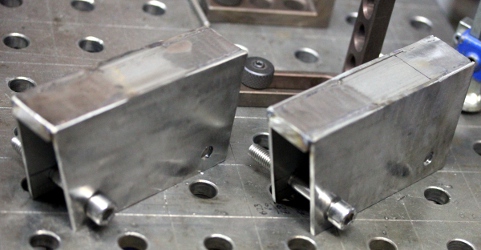
- 25.06.2014: The solenoid assemblies from Syndyne came flowing in. Construction
of the plucker mechanism can be started.
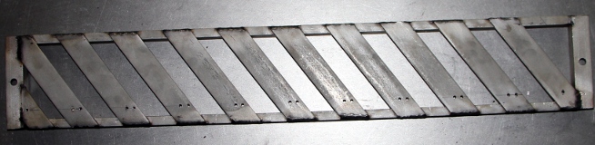
 Welding
plan drawn out.
Welding
plan drawn out.
- 26.06.2014: Welding of the plucker chassis and start drilling of the mounting
holes.
- 27.06.2014: Further work on the plucking mechanism: cutting unneeded parts
from the Syndyne assemblies. Finishing drilling work of the holes. Countersinking
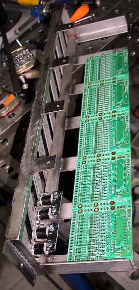
all holes for M3 bolts. Design of a carrier for the six PC boards. These board
will be mounted in a horizontal plane, for ease of maintenance and programming.

- 28.06.2014: Finishing all welding on the plucker chassis.
 . A box full of 6V bulbs with E14 fittings found on a street flea market here
in Ghent.
. A box full of 6V bulbs with E14 fittings found on a street flea market here
in Ghent.
- 30.06.2014: Start coding of the PIC firmware, as the complete plucking mechanism
has to be up and working before we can go on making the actual zither. Version
1.0 of the firmware ready to be tested. Starting implementation of testcode
in GMT. Board 1 wired, soldered and programmed.
- 01.07.2014: Further soldering works on the boards, no less than 252 MOSFETS
to be soldered... Mounting of the solenoid assemblies on the chassis done
by Mattias Parent.
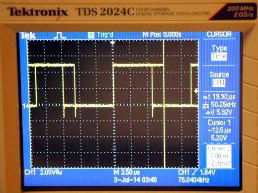
- 02.07.2014: Continuing soldering works of the boards... Construction of
the red copper power rails. Mapping error in the lookup tables found and repaired.
Measurement of the loop-speed of our firmware under no-midi input conditions:
4 microseconds. With no midi coming in, the square wave frequency measured
at a bit-toggling port (RA4) is 125kHz. Hence the idle loop time is 4 microseconds.
With fast midi in, and commands for all 5 strings and lights, the loop time
becomes 7.4 microseconds. The worst case scenario would be all 5 strings on
at the same time, and thus all five timers running in the code, a scenario
in which the loop speed goes up to 12.4 microseconds. Thus, this would be
the worst case jitter to expect on the duration of the velo-pulse lengths
generated. Measurements were taken with our Tektronix TDS2024C oscilloscope.
(200MHz, 2GS/s). We can be pretty confident that our code will not miss any
commands and that the jitter will remain below 1% of the soll-values.
- 03.07.2014: M4 threaded standoffs ordered from Farnell. Start wiring of
the solenoid assemblies. Version 1.0 of the firmware for all the boards written
and programmed into the microcontrollers.
- 04.07.2014: All wiring done. Start of the first tests. As we didn't even
start making the actual stringed instrument, we perform the tests with a Zither,
placed in an upright position. We use a lab power supply adjusted to 6 V for
the hold voltage and a -36 V power supply for the negative pulse voltage.
We observe excessive bouncing of the plectrum/anchor combination. The pulse
duration's have to be scaled down in the firmware.
- 05.07.2014: Firmware adjusted according to our measurements. String mapping
and therewith ambitus changed to start from midi note 40 (low E). Thus the
instrument should become reasonably compatible with the guitar. We ordered
a complete set of Dupont qanun strings. These sets come in 7 different thickness':
1.25 mm, 1.1 mm, 1mm, 0.9mm, 0.8 mm, 0.75 mm, 0.65 mm. Sets of banjo strings
would be a good alternative.
- 06.07.2014: Designing a new tuning mechanism, as our experiments with using
mandolin tuning screws turned out badly. Start construction of the required
power supplies. A first prototype of a tuning mechanism was constructed, starting
from a stainless steel M4 x 50 bolt.
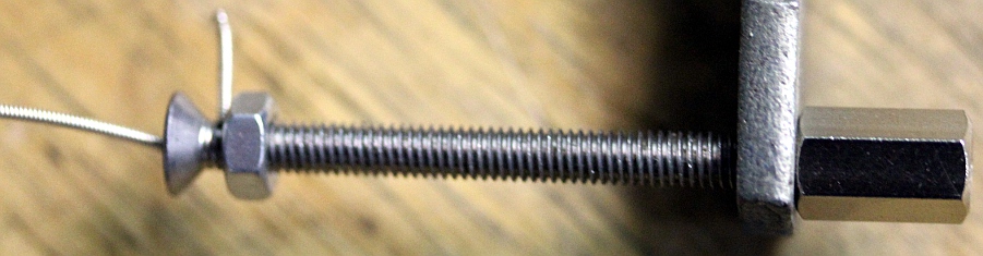 With
such tuning pegs, it would be imaginable to give the instruments two strings
for each note, as space requirements are really minimal. Another consequence
of using such tuning pegs is that it will lead to a pure rectangular soundboard
and instrument instead of the usual trapezoidal shape. It is mandatory that
the tuning pegs are fully in line with the strings. Giving the upper part
a staircase shape would be possible but involves a lot of welding and cutting
work.
With
such tuning pegs, it would be imaginable to give the instruments two strings
for each note, as space requirements are really minimal. Another consequence
of using such tuning pegs is that it will lead to a pure rectangular soundboard
and instrument instead of the usual trapezoidal shape. It is mandatory that
the tuning pegs are fully in line with the strings. Giving the upper part
a staircase shape would be possible but involves a lot of welding and cutting
work.
- 07.07.2014: Calculation and design of the power supplies.
 This will be mounted on the bottom plate, 500 mm wide.
- 08.07.2014: Construction of the tuning pegs explained to Mattias such that
he can prepare a full set. Start construction of the power supply assembly.
- 09.07.2014: Heavy electrolytic capacitors came flowing in. Construction
of the power supply can continue.
- 11.07.2014: Further work on the power supply and bottom chassis, including
a midi-hub board. A full day of drawing, drilling and milling on the bottom
plate. Wiring will be for tomorrow...
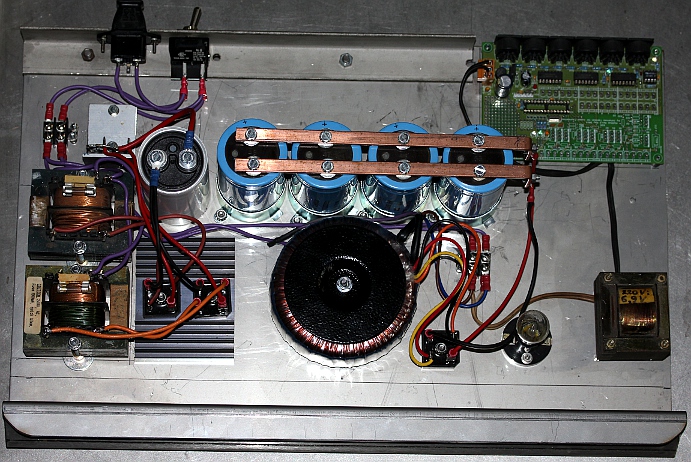
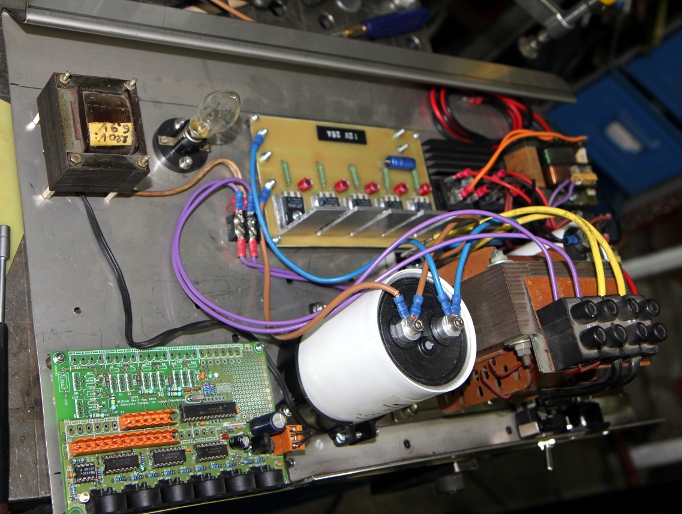
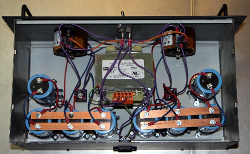
- 12.07.2014: Wiring the power supply unit. After testing, it came out that
the two assumed 'identical' 6V transformers (indeed, a former Radio Shack
product...) give very different output voltages: 6.7V and 8.8V... This may
cause trouble. To be checked. This is what the power supply assembly looks
like:

- 14.07.2014: Midi-hub board soldered. So now we have the required +5V available
and thus testing can continue.
- 26.07.2014: A full set of Qanun strings, ordered from Turkey, came in.
- 01.08.2014: Work on <Zi> taken up again. On connecting the new power
supply something seems to go very wrong... the negative power source draws
high current and the mosfets became extremely hot... Did we cause a short
somewhere? Apparently we had a short on the power buslines under the boards.
But also, we have to check the P-channel mosfets: BS250 cannot be used as
they have a maximum Vds voltage of only -45V. The BSP254A allows up to -250V.
ref.: datasheet.
- 02.08.2014: Further research into the origin of the fault condition, Failure
traced: the negative going power MOSFET, gets Vgs > > 20V and thus the
gate of the MOSFET melts down. This made us discover a general flaw in our
pulse/hold designs so far.
- 03.08.2014: Measurement circuit build up to verify our hypothesis. In future
circuits we need a voltage divider and a zener protection diode to the gate
of the velo-driver MOSFET. If we use IRL640, the zener diode should be rated
for 10V. A IRF540 can also be used, and needs a zener with a voltage value
between 10 and 20V. Also the P-channel MOSFET must be BSP254A. Boards 2, 3,
4, 5, 6: all IRL640 replaced with IRF540. On board 4 we soldered 14 Zenerdiodes.
As long as the negative voltage doesn't get much larger than -48V, the existing
unmodified circuit works well.
- 04.08.2014: As on board 1 none of the IRL640 were defective, we just added
gate protection zener diodes 6V2 on the solder side of the PC board. So, at
this point only boards 1 and 4 are protected with Zener diodes. All boards
mounted again in the plucker assembly. Test code in GMT adapted such that
we can test each board individually.
- 05.08.2014: As we want to avoid having to unsolder that many mosfets again,
we designed and build an experimenting board for tests, measurements and evaluation:

- 06.08.2014: Tests with different plectrums and materials that can be used
as plectrums. Design of a new laboratory power supply with high current and
high voltage range. It should withstand highly inductive loads, this not being
the case for commercially available laboratory power supplies...
- 09.08.2014: Here is a link to our
app note for this new hefty power supply. The circuit diagram looks like
this:
- 10.08.2014: We also designed and a more universal pulse/hold board with
12 outputs, so enough for a musical octave if applied to player pianos and
organs. Here is the PCB design:
 This design should be reduced to 50% for production on a PC board. The diodes
used are U12C020A types: dual diodes in TO220 housing with a common anode.
Here is their data
sheet. The hold-mosfets are IRL640 and the velo mosfets IRF540. Note that
we produced these boards only for research reasons, not withstanding that
they may replace existing designs at some point.
This design should be reduced to 50% for production on a PC board. The diodes
used are U12C020A types: dual diodes in TO220 housing with a common anode.
Here is their data
sheet. The hold-mosfets are IRL640 and the velo mosfets IRF540. Note that
we produced these boards only for research reasons, not withstanding that
they may replace existing designs at some point.
- 11.08.2014: Construction of a 500
Watt dual power supply, required for testing our circuitry.
- 12.08.2014: Board 2, 3, 5,6: 10V zener diodes soldered on board. Powered
up with the high negative voltage (60V) ... smoke stacks from board 4. What's
the matter now? Again a MOSFET gone to heaven.
- 13.08.2014: Finally... we got all boards and all pluckers to work well electrically
and on -60V. For future designs though it might be better to considers IGBT's.
For now all velo MOSFETS are IRF540. All zener diodes are 10V. We upgraded
our article on 'Expression
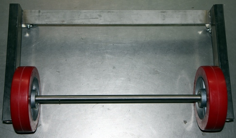
control in automated instruments' with our new findings. Drawing of the
wheel base and the mounting of the plucker assembly. Cutting and drilling
work on the parts. Preliminary mounting of the back wheels, building height
80 mm.
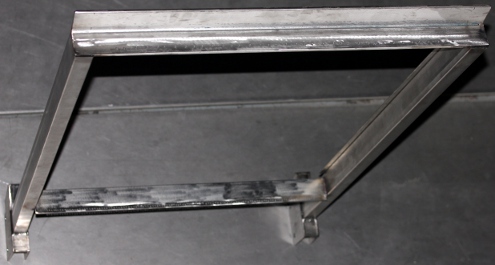
- 14.08.2014: Start construction of the wheelbase. Precision TIG-welding works
on the welding table, as sizing errors have to be kept below 1 mm. By the
end of the day, the chariot and the plucker holder are finished. Power supply
mounting works O.K., just two M6 bolt hold it in place, as the assembly slides
over the wheel spindle.
The 'harp' will be constructed such that it is a detachable and exchangeable
part. This makes is possible to fit a harp with twice as long strings and
thus sounding an octave lower, or exchanging it for one with steel strings...
Anyhow we will start-off by designing and making a 'harp' of the smallest
possible sizing: longest string = 650 mm (sounding length).
- 15.08.2014: Start construction of the zither properly speaking. Width between
vertical poles: 623 mm. Tuning peg holder: Aisi 304, L- 50x50, length 683
mm. String holder underside: length 623 mm. The vertical poles will be cut
from 30 x 50 profile, 1000 mm high. All holes on the string holder profile
drilled (3 mm holes).
- 24.08.2014: Tuning peg holder drilled. Vertical poles cut out. Main frame
for the harp welded together.
- 25.08.2014: Mounting feet for the harp designed and cut out.
 These must allow for a 20 mm slide to make adjustment of the strings with
the pluckers easier.
These must allow for a 20 mm slide to make adjustment of the strings with
the pluckers easier. 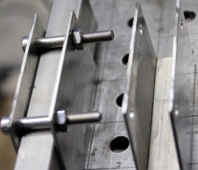 Big
mistake: we welded one of these feet in the wrong direction... we will have
to saw it off and start again...
Big
mistake: we welded one of these feet in the wrong direction... we will have
to saw it off and start again...
- 26.08.2014: Welding the feet on the harp. Mounting
test. We may need to add M10 setscrews on the 10 mm thick base plate of the
feet. First cut out of a sound board in expanded polystyrene. First experiments
with strings, using stranded beading wire. This sounds very good, a bit banjo
like.
 Although we will not use this as string material, this stranded beading wire
really sounds excellent. Here is a picture of the rolls on which it is sold:
Although we will not use this as string material, this stranded beading wire
really sounds excellent. Here is a picture of the rolls on which it is sold:
- 27.08.2014: First attempts to mount real Qanun strings. There are some problems
with the tuning however, as many sources are confused with regard to the octave
position of the notes. We asked Xavier Verhelst to do some research: http://www.georgedimitrisawa.com/qanun.html
(link does not work anymore) this source quotes 26 sets of triple strings
with a range of 3 octaves and a fifth, from G (midi 41), an octave and a fourth
below middle C, to D (midi 86), 2 octaves and a second above middle C. Clearly
wrong as G ought to be midi note 43. A second source, http://en.wikipedia.org/wiki/Qanun_(instrument)
states: Qanuns used in Turkey have 26 courses of strings, with three strings
per course. It is played on the lap by plucking the strings with two tortoiseshell
picks, one in each hand, or by the fingernails, and has a range of three and
a half octaves, from A2 (midi 33) to E6 (midi 76). The dimensions of Turkish
kanuns are typically 95 to 100 cm (37-39") long, 38 to 40 cm (15-16") wide
and 4 to 6 cm (1.5-2.3") high. However, this seems very unlikely, and probably
everything should be an octave up. A thirth source is: http://www.loc.gov/item/afccc.a4243b1
(link does not work anymore) audio file (wav & mp3) with the tuning (Armenia,
1937). Further at http://tribes.tribe.net/quanoun/thread/a52eb103-ee1f-4281-a167-8513f86701ea
(link does not work anymore) where a user thought that the lowest note given,
D (midi 38) ought to be G ( midi 41). The source http://www.atlasensemble.nl/assets/files/instruments/Qanun/Qanun%20by%20Bassem%20Alkhouri.pdfgives
G2 (midi 31) to D6 (midi 74), but in our opinion this also is an octave wrong,
a very common mistake amongst guitarists... So we tried out a tuning
starting from midi 50 (D) for the lowest note. This leads to following ambitus:
- 28.08.2014: As the stringing can be changed by the users, we decided to
implement a controller to set the tuning. This avoids having to use the robot
as a transposing instrument. It requires a revision of the firmware for all
6 microcontrollers though.
- 29.08.2014: First set of 11 strings mounted on the instrument. Bridges sawn
out, starting from a collection of folk guitar bridges we had in stock. The
inlay in hard plastic can be used for height adjustment of the individual
strings.
- 30.08.2014: Tube keys 7 mm purchased to make a tuning key for the instrument.
It appears that the Styrofoam bends too much under the force of the strings,
making the tuning very unstable. So we will need to add a reinforcing bar
on the backside. Also the bridges need to have a larger bottom surface.
- 31.08.2014: All strings taken off again in order to make it possible to
weld two 683x30x30 mm, 3 mm thick T profiles on the backside, preventing the
polystyrene from bending too much.
- 01.09.2014: 22 Strings mounted. 20 new bridges made from hardwood. 16 more
tuning pegs to be made on the lathe.
- 02.09.2014: We made a string order mistake. Twelve strings have to be taken
off and replaced. Here is what it should be (double checked...):
 Mattias Parent called in to help us out removing and replacing the strings.
More tuning pegs
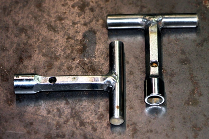
made on the lathe. By the end of the day, all strings mounted. Two
tuning key made, starting from Beta tubular keys 6/7mm. These had to be hollowed
out with a 4 mm hole, at least 50 mm deep. Left
to be done: definitive bridges, construction, placement, adjustment. On the
picture, our experiments with different shapes and models of bridges can be
seen. Here is a detail of the tuning pegs:
Mattias Parent called in to help us out removing and replacing the strings.
More tuning pegs
made on the lathe. By the end of the day, all strings mounted. Two
tuning key made, starting from Beta tubular keys 6/7mm. These had to be hollowed
out with a 4 mm hole, at least 50 mm deep. Left
to be done: definitive bridges, construction, placement, adjustment. On the
picture, our experiments with different shapes and models of bridges can be
seen. Here is a detail of the tuning pegs: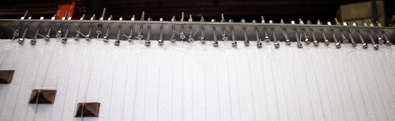 And this shows the knotting of the strings and the lower bridge:
- 03.09.2014: First attempt to tuning all strings... a tedious job.
- 04.09.2014: All combs redone from equilateral triangle hardwood material.
First attempt to assemble the complete instrument, by bringing the harp in
front of the plucker mechanism. Now the mounting and cutting of the pluckers
can start off.
- 05.09.2014: If we want to get the effect of a triple strung instrument,
we might consider to realize this electronically. By picking up the sound
(triggered by a note-on command) and delaying it 20ms or so and sending it
back two times - with some phase shift- after amplification to a contact-driver
mounted on the soundboard, it would become possible. This entails the addition
of an ARM processor though, unless we went for analogue bucket brigade delay
lines. These electronics could find a place on the backside of the soundboard.
- 06-15.09.2014: Experiments and research with regard to the best plucker
shape, material and construction. The alignment promises to become an extremely
difficult and tedious task. So far, bone material as used on guitar bridges
seems to work best.
- 16-17.09.2014: Seems that the threaded holes in the Syndyne plucker solenoids
have a non-metric #6-32 UNC thread... Obviously the corresponding bolts are
extremely hard to find on the market here... Searching through our junk packs
in an attempt to dig up some 38 #6-32 bolts... The diameter of such bolts
is 3.4 mm, so we have to enlarge the 3 mm holes in the plectra a bit.
- 18.09.2014: As we were not charmed by the sound of the highest strings,
we decided to add a bridge over them to increase the angle under which these
strings touch the sound bridges. This bridge was made from massive stainless
steel rod 8 mm thick welded on fastening plates allowing fixation on the frame
of the harp.
- 19.09.2014: As the results of the added crossbar for the highest 10 strings
were very positive, we made another crossbar for the next highest series
of ten strings. We may even add a thirth crossbar. An inconvenience is now
that if the Styrofoam soundboard has to be replaced, all these crossbars need
to be unscrewed.
- 20.09.2014: All three crossbars made and mounted. The lowest one is 680
mm long, the second 690 mm and the last 700 mm.
- 21.09.2014: Threading M4 holes for the stop plates at both ends of the wheel
spindle. Stop plates mounted. These parts still need to be polished.
- 23.09.2014: Mounting of the 38 plectrums. Start adjustments...

- 24.09.2014: Works on <Zi> on hold for a while...
- 22.10.2014: The three crossbar bridges fixed with M5 x 60 bolts.
- 01.12.2014: Mounting of plectrums confined to Mattias Parent.
- 09.04.2015: Experiments performed with increased mass of the anchors in
order to increase plucking force. We can use small cube neodium magnets on
the one side, or try to obtain the equivalent through a different coding in
the firmware. We wired up a prototype board to perform these experiments.
The result were not worth the effort though.
- 23-24.04.2015: Further research and experiments by Mattias Parent.
- 25.04.2015: Board 1, output 6 velo pulse MOSFET replaced as the old one
died due to a short we caused during an attempt to adjust the plucking mechanism.
- 06.08.2015: After many hours and days of experimenting we came to the conclusion
that the mechanism for the pluckers is unworkable. So we started a new design,
using linear bi-directional solenoids.
- 17.08.2015: Drawing a new design for the pluckers.
- 18-21.08.2015: Design of new electronics to be used for bi-directional solenoids.
Here is a circuit drawing:
 As the polarity of the solenoids needs to be reversed after each stroke, we
need H-bridge drivers. The old and proven L298N came to rescue here. The big
advantage of this approach is that power consumption is minimal, as no hold
current is needed anymore. However, the current for each movement is 3A! Here
is a 200% PCB for the above circuit:
As the polarity of the solenoids needs to be reversed after each stroke, we
need H-bridge drivers. The old and proven L298N came to rescue here. The big
advantage of this approach is that power consumption is minimal, as no hold
current is needed anymore. However, the current for each movement is 3A! Here
is a 200% PCB for the above circuit:  For
the solenoids we bought to be tested, we need insulating washers with a hole
of 2 mm and an outer diameter of 10 mm. Thickness around 0.5mm. This needs
some hunting, unless we can make them ourselves on the lathe.
For
the solenoids we bought to be tested, we need insulating washers with a hole
of 2 mm and an outer diameter of 10 mm. Thickness around 0.5mm. This needs
some hunting, unless we can make them ourselves on the lathe.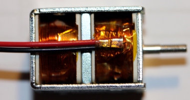
- 22.08.2015: Plectra made from nylon staff material on the lathe. Experiments
with plucking carried out on an old zither with steel strings. The plucking
does work indeed but we notice a click-noise on each position change of the
solenoid. Seems to be unavoidable.
- 23.08.2015: Further redesign of the qanun. Considering to use the prototype
1 assembly for another robot, maybe <Tinti>,
using tiny bells... New stainless steel piece cut out to serve as a holder
for the solenoids 682mm wide, T-profile, 3mm thick. It ought to mount on the
existing carrier structure with two M8 bolts. The carrier plate for the five
new PC boards should be bolted or welded in this same bar.
- VERSION 2:
- 30.09.2015: The missing and ordered bistable solenoids came in from Conrad,
so the works on the new plucker mechanism can continue.
- 02.10.2015: Helene Wolf contacted to help out with the design and cutting
of a new comb. As a cembalo maker, she ought to have the experience.
- 03.10.2015: Prototype board for the new solenoids etched, drilled and soldered.
We can test the first 8 solenoids if we have also the firmware ready. Work
for tomorrow...
- 04.10.2015: Firmware written for the first plucker board. Note repeats using
key pressure implemented. Here is the source
code.
- 05.10.2015: Photosensitive PCB's ordered from Farnell such that we can produce
the remaining four boards. Redesign of the power supply.
 The 12V transformer is clearly overdimensioned (200VA would have reached out)
but we simply had it at hand and thus decided to use it. PCB designed for
the five LT1084 regulators. The heat sinks are underdimensioned but that should
not be a problem as the supply needs only to be rated for momentary peak currents.
The 12V transformer is clearly overdimensioned (200VA would have reached out)
but we simply had it at hand and thus decided to use it. PCB designed for
the five LT1084 regulators. The heat sinks are underdimensioned but that should
not be a problem as the supply needs only to be rated for momentary peak currents.
 The PCB here
is at 200% and should be reduced to 50% before printing and exposing.
The PCB here
is at 200% and should be reduced to 50% before printing and exposing.
- 06.10.2015: Exposure, development, etching of the power supply board as
well as the four remaining solenoid driver boards. Soldering and testing of
the 25A power supply board. Mounting of the hefty 500 VA transformer and 220
mF Kemo capacitor on the bottom plate.
- 07.10.2015: Test of the 12V/25A power supply board. Found o.k.
Drilling of the holes in the four to be done solenoid driver boards. Board
2 and soldered.
- 08.10.2015: Continuing soldering work on boards 4 and 5. Running out of
stock on some components: diodes, connectors. PCB for the driver board slightly
improved. Instead of using 8 diodes for each driver, we better use two rectifier
bridges. This change will of course only affect future production boards.
- 09.10.2015: Finalizing soldering work on boards 4 and 5.
- 18.10.2015: Helene Wolf will make a new comb for <Zi>... The upper
comb:
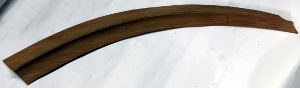 and the one
for underneath:
and the one
for underneath: 
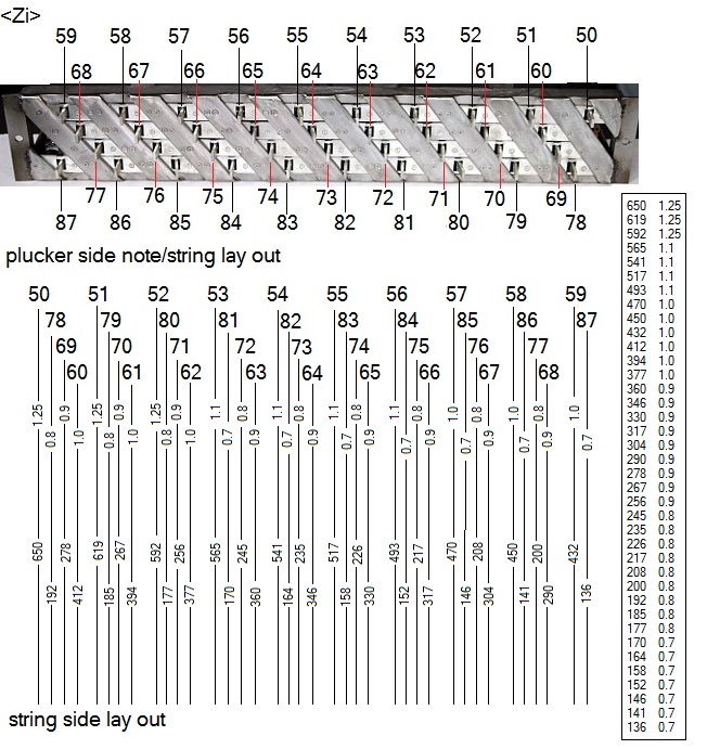
- 10.10.2015: All PCB's ready. Loading firmware for testing. Design of a carrier
board for these five PCB's. Width should be 580 mm. Reminder: distance between
the strings is and should be 15.21 mm. Here is a new drawing for the solenoid
assembly, dictating the new sizing of the strings:
- 15.10.2015: Mounting plate for the PCB's finished.
- 06.11.2015: All bi-directional solenoids glued on the T-bar with blue Loctite
gasket silicone glue. There is a half-coil offset to the left, so the plucking
will happen on the left side of the strings.
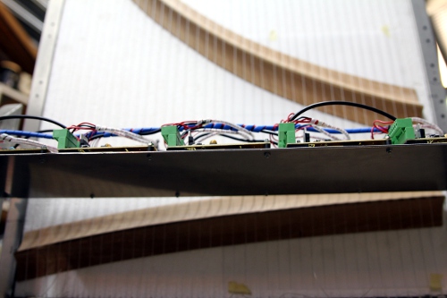
- 07.11.2015: Start wiring of the solenoids to the boards with Weidmueller
connectors.
- 08.11.2015: Wiring of the midi and 5V power connectors.
All wiring done... The re-assembly on the chassis can start.
- 09.11.2015: All boards connected to the bottom plate. Data and power connections
finished. First tests of the new hardware. GMT testcode rewritten for the
new hardware. Firmware for the five boards adapted to the newest implementation.
This be version 1.0. First testing reveals a bug on note 53 (Zi1 board) and
heating of the drivers for notes 58 to 61 (Zi2 board). As the firmware for
all PIC's is basically the same, we first will have to look for some hardware
bugs.
- 10.11.2015: Two L298 drivers replaced on board Zi2. We had a short on the
PCB on the output pins...
- 11.11.2015: Further debug sessions on the PIC firmware. Shaky behavior of
board Zi3 solved: we forgot the 10k pull up resistor on pin1 of the PIC microcontroller.
Shakiness of note 54 was due do a bad solder connection on one of the protection
diodes on board Zi1. Plucker reset controller added in the firmware. We are
now at firmware version 1.2. Now we still have a problem on board Zi1 with
note 53. Must be a hardware problem. Velo's increased a factor 2. Now at firmware
version 1.21. Testcode in GTM extended. By the end of the working day, everything
seems to be working fine, except for note 53. However we found the bug: the
inverter chip is failing. Replacement will be for tomorrow.
- 12.11.2015: 7667 bufferchip replaced and everything works fine now. We have
no idea as to what caused the 7667 to fail... infant mortality?
- 14.11.2015: Start mounting plectrums but we are falling out of M2 nuts...
Plucking test performed used a balalaika. Not very promising...
- 16.11.2015: Fresh M2 nuts purchased at MEA. Mounting of all plectrums with
two stainless steel M2 nuts on the solenoids.
- 12-28.12.2015: Construction of a new bridge by Helene Wolf.
- 11.01.2016: Work on Zi taken up again.
- 26.01.2016: New bridges made by Helene Wolf presented and found to be excellent.
Start restringing the instrument.
- 19.02.2016: Sliding feet of the soundboard cut open again as the mechanism
was too stiff.
- 24.02.2016: Adjustment studs drilled and mounted to allow precise positioning
of the soundboard versus the plucking mechanism. For now using M6 threaded
rods, but this may become a larger size later on.
- 29.02.2016: Further restringing and gage checking. Placement of the new
bridges with Helene Wolf.
 Looks
like we will have to order some spare 0.8 mm diameter Qanun string material.
Looks
like we will have to order some spare 0.8 mm diameter Qanun string material.
- 01.03.2016: Cutting of the standing feet for the harp such that it can be
moved further backwards.
- 02.03.2016: Some adjustment required for the stand-off between harp and
plucking mechanism.
- 15.10.2016: All experiments with suitable plectrum material failed. The
problem that plagued our first and rejected design is reappearing: the solenoids
do not have enough power in the mid position. Furthermore, it appears unfeasible
to adjust the plucking distance reliably. As in top of all this bad luck,
we also lost all funding due to a bad and big-ego oboist, Piet Van Bockstal
that issued a negative and canceling advise for funding against the Logos
Foundation. So, the project has to be placed on hold.
- 09.10.2024: <Zi> project taken up again. Considering to use linear
motors instead of solenoids. These for sure have enough power but they are
pretty slow... In principle we could use the same electronic circuits to drive
the motors. The firmware needs a complete revision and note repetitions seems
to be impossible, unless we allow only very slow repetitions...
- 10.10.2024: Two new PCB's etched and drilled.
- 11.10.2024: One board soldered. PCB layout improved.
- 12.10.2024: Second board soldered. Tests of the few firmware.
- 12.11.2025: Work in the zither taken up again. The very successful poltergeist
mechanism we made for <Ubu>, gave us the idea to use some of the hundredths
of Binder 12V solenoids we have in stock as rebounce hammers. To be successful
we have to replace the springs with a much stronger type. The original springs
have following sizes:
 The
thread for mounting the solenoids is M10x1 (metric extra fine).
The
thread for mounting the solenoids is M10x1 (metric extra fine).
- 13.11.2025: It becomes mandatory to equip the Binder solenoids with much
stronger springs. Experiment performed: using a pressure spring (Fabory stock
item) 0.5 x 6.5 x 20, shortened to 7.5 mm (4 turns), works well with a supply
voltage of 48 V. Duty cycle should be kept smaller than 5%. Current is 240mA,
the coil resistance is 200 Ohms. Peak power follows as 11.5 Watt. For the
control we can use some older pulse-only PCB's. As there are 25 chromatic
strings, we can even save some pins for the ICD. Each board is designed for
16 outputs. Application moved to the <Zibalo>
project...
- VERSION 3:
- 11.01.2026: Looks like we have to abandon the original <Zi> project
altogether. The documentation from all older experiments and building phases
can be found in the legacy webpage zi_qanun.html.
Plucking strings sofar has been unsuccessful... Can we use and recycle the
solenoid assembly to activate thin springs? First series of experiments carried
out.
- 12.01.2026: <Zi> fired up again. All solenoids seem to be working
fine. Springs ordered from Temu in China... <Zi> may become a completely
different robot altogether now. Shouldn't we rename it <Zip>?
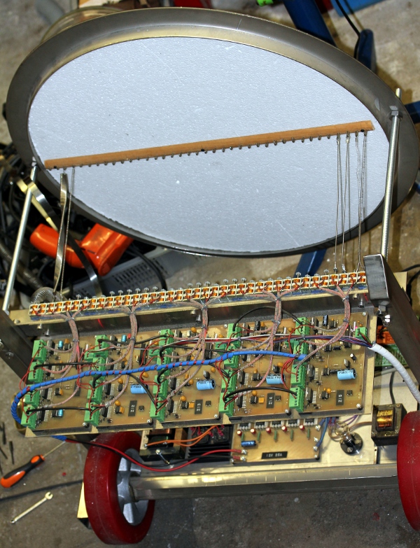
- 20.01.2026: Assortment of springs arrived from Temu. Testing for sound.
Due to the very low forces the solenoids are capable of delivering, the sound
output will have to remain pretty low. Start construction of a comb for 38
springs.
- 21.01.2026: Comb with hooks: work continued...
- 23.01.2026: After immunotherapy in the hospital yesterday, continuing work.
Styrofoam resonator mounted and preliminary testing with some springs. Promises
are positive so far...
- 24.01.2026: Further selection and mounting of different springs. We do not
have a wide enough assortment of different springs though. So far already
22 springs mounted. Distance holders for the resonator assembly made: stainless
steel tube 20 mm diameter, 2 mm thick. Lenght: 310 mm. New icon designed for
use in GMT:

- 25.01.2026: Some more suitable springs digged up and mounted. Two white
12V LED lites mounted left and right on the solenoid bar. The are mapped on
notes 88 and 89 but will not be controllable for the users. They will work
in function of the activated springs only.
- 26.01.2026: Re-design of the midihub board. Construction of a strong 6V
frontal light, starting from a recycled motorbike frontlight. The bulb is
Halogen 10W 6V, Radium Skylight RJ1006.
- 27.01.2026: Soldering works on the midi hub board. At the same time board
patched and modified such that we can now implement parsed midi out on the
weidmueller connectors. Firmware for the hub board completely rewritten. In
the air flying wires on the solderside of the board secured with epoxy compound.
Firmware tests passed on the modified board.
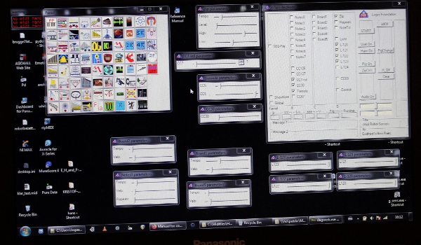
- 28.01.2026: Testcode in GMT added. <Zip> fully implemented in GMT
now. Hub board placed back in the robot.
- 29.01.2026: Verdere ontwikkeling van de firmware. Onderzoek naar de mogelijkheid
om klankversterking in te bouwen. De akoestische geluidjes van de veren zijn
weliswaar vrij goed, maar te stil om bruikbaar te zijn in het robotorkest.
- 30.01.2026: Alle elektromagneten zijn nu van veren voorzien, weliswaar niet
allemaal optimale veren... Proeven met een piezo-kontaktmikrofoon op de kam
en diverse types luidsprekers. Een flinke woofer ware ideaal maar daarvoor
hebben we niet voldoende plaats. Een JBL 'University Sound' gevouwen hoorn
testten we ook, maar dat klinkt te schriel. Uiteindelijk opteren we voor een
hoornluidspreker van chinese makelij. Die kan een plaats krijgen onderaan.
Een besturingsmogelijkheid voor de amplitude van de versterking dringt zich
nu op. Kunnen we weer een optor gebruiker zoals eerder toegepast in <Pianet>
en <Chi> ? We hebben nog enkele Vactrols op voorraad en o.m.nog 1 exemplaar
van de VTL5C1 Vactrol, met een dynamisch bereik van 100dB. Hier
is het datasheet.
- 31.01.2026: De chinese hoorn klinkt bij nader toezien toch ook wat benepen.
Een stokoude Polyplanar speaker (gemaakt in styrofoam en in de vroege jaren
'70 gekocht bij Radio Shack...) klinkt al heel wat beter, maar levert wel
nogal wat montage problemen en kwetsbaarheden op.
- 01.02.2026: Kemo amplifier modules besteld bij Conrad. Op het hub board
alvast 10-bit PWM geimplementeerd voor de aansturing van de Vactrol. Die wordt
op het hub board gemonteerd. We gebruikten het laatste exemplaar van het type
VTL5C1. Het is niet meer verkrijgbaar.
 De
audio schakelingen komen er nu zo uit te zien:
De
audio schakelingen komen er nu zo uit te zien: 
- 02.02.2026: Firmware voor het midihub board herschreven, nu met implementatie
voor tremolo middels midi controllers 5 en 6. Voor de voeding van het audiogedeelte
kunnen we een oude Acer laptop voeding gebruiken. Die geeft iets meer dan
3 A stroom bij een spanning van 19V. Op het hub board moeten we nu wat plaats
zien te maken voor een 6 V relais waarmee we de audiokomponenten kunnen aan
of uit-schakelen. Een JZC-22F relais met een schakelvermogen van 7 A hebben
we nog op voorraad. De gelijkstroomweerstand van de spoel is 84 Ohm. De stroom
in bekrachtigde toestand is derhalve beperkt tot 72mA.
- 03.02.2026: In afwachting van de levering van de Kemo modules door Conrad,
alvast een schakeling met de TDA stereo amp en twee Vactrols uitgewerkt. Hier
zijn zowel schema als PCB ontwerp:
 Kan van pas komen als we later
een versie met twee speakers en Leslie zouden willen bouwen. De vactrol types,
NSL32SR3 hebben we nog ruim op voorraad.
Kan van pas komen als we later
een versie met twee speakers en Leslie zouden willen bouwen. De vactrol types,
NSL32SR3 hebben we nog ruim op voorraad.
- 04.02.2026: Levering van Conrad aangekomen. We kunnen weer verder wat bestukken.
Wat te verwachten was, deed zich uiteraard alweer voor: motorboating in het
audio gedeelte. We moeten dus een gebufferde voedingsspanning voorzien voor
de voorversterkermodule. De gain met tweemaal 40dB blijkt ook veel te groot
te zijn. Volumepotmeters of trimmers zijn dan ook wellicht aangewezen. Eerste
tests met de audioschakeling: het blijkt te werken, maar de belasting voor
de piezo met 100 Ohm en 4.7nF is wel wat te extreem bemeten. Ook de belastingsweerstand
van 1 kOhm voor de Vactrol mag naar 2 kOhm gebracht worden. Werk voor morgen...
Controller 67 werkt zoals verwacht, ook de lichten op noten 120 en 121 werken
nu zoals voorzien. Er is nog ruimte voor drie lichten nu.
- 05.02.2026: Eertste voorlopige demonstratie van <Zip> voor de medewerkers
Hans Roels en Mattias Parent. Dokumentatie van de bedrading van het midi-hub
board aangepast aan de nieuwste versie:
 De repetitiesnelheden mogen -indien mogelijk- zeker nog verdubbeld worden.
Ook de maximale tremolosnelheid mag ook wat groter worden. Het amplifier board
-gemonteerd op een stukje polykarbonaat- ziet er nu zo uit.
De repetitiesnelheden mogen -indien mogelijk- zeker nog verdubbeld worden.
Ook de maximale tremolosnelheid mag ook wat groter worden. Het amplifier board
-gemonteerd op een stukje polykarbonaat- ziet er nu zo uit. 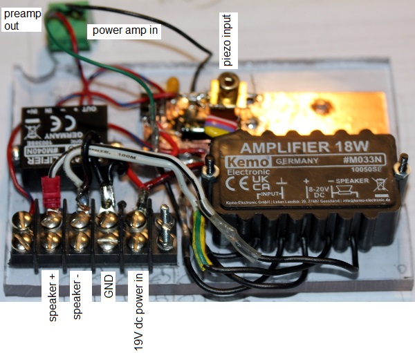 .
We maakten meteen ook een nieuwe piezo kontaktmikrofoon, voorzien van een
M3 bevestigingsgaatje waarmee hij spannend op de kam kan worden vastgemaakt.
.
We maakten meteen ook een nieuwe piezo kontaktmikrofoon, voorzien van een
M3 bevestigingsgaatje waarmee hij spannend op de kam kan worden vastgemaakt.
- 06.02.2026: Piepschuim resonator vervangen door een nieuw, vers exemplaar
met assistentie van Bert Vandekerckhove. Kam vastgezet met 5 M3 x 50 boutjes
en piezo kontaktmikrofoon bevestigd aan het middelste boutje tussen kam en
styrofoam. Oogjes voor de bevestiging van de veren wat meer dichtgebogen zodat
de veertjes niet zo gauw losspringen. Alle zes pics opnieuw geprogrammeerd,
getest en o.k. bevonden. Links naar de source kode en de hex dumps toegevoegd
aan deze webpagina.
- 07.02.2026: Konstruktie van twee rode LED eenheden, elk bestaande uit 3
1W Led's in SMD uitvoering. De stroombegrenzingsweerstand namen we op 2.2
Ohm, zodat een lange levensduur van de LED's zeker gegerandeerd kan worden.
Deze worden ingezet als licht 122 en 123. Bij metingen van de stroomopname
in ons labo konstateerden we iets merkwaardigs: de LED stroom is mede een
funktie van de lichtreflektie van de LED's! Wanneer meer licht gereflekteerd
wordt, stijgt de stroom tot bijna de dubbele waarde. Deze observatie is echter
van geen enkel belang voor <Zip>. Demo filmpje opgenomen voor verspreiding
via Facebook. Verdere muzikale exploraties van de mogelijkheden. Dit is het
test- en speelinterface binnen onze GMT omgeving:
- 08.02.2026: Hier is een kleine 4 minuten lange demo
van <Zip>. Extra 6V 4.2W halogeen lamp met E10 socket gemonteerd
op het basischassis. Mapping op noot 124. Opruimen... de nageboorte van elke
nieuwe robot.
-
-
-
TO DO:
- Final (re)construction of the instrument
- mounting and further implementing lights on notes 122,123 and 124.
- selecting better good sounding springs.
- replacing the styrofoam board with a new and clean one.
- Final scaling of the velocities and repeat frequencies to realistic
values.
Last update: 2026-02-08
by Godfried-Willem Raes
The following information is not intended for the general public nor is
it required for composers wanting to make use of our <Zip> robot,
but is essential for maintenance and servicing of the robot by our collaborators.
It also might be usefull for people that want to undertake similar projects.
Feedback is mostly welcomed.
Technical drawings, specs
and data sheets:
Power supplies:
- +5 V DC - 1A(Logic and microcontrollers), Voltage regulator (a low-drop
type) is on the midi-hub board.
- +12V DC - 25A (solenoids)
- +6V DC , 60 VA (lights)
- +19V DC, 3A (audio circuitry)
PIC firmware:
-
Wiring & circuit details midihub board:

The hub board, with all
components mounted.
Circuit details solenoid driver boards:
-
Schematic:
- PCB:
- Board view:
- Power supply:
The PCB for the 25A/12V supply is:
 [source has scale 200%]
Audio amplification and control assembly:
-
Bi-directional solenoid or linear motor assemblies:
- Prototype 1 (rejected) : Syndyne, each coil has 28 Ohms DC resistance.
The 100% duty cycle voltage is specified as 14 V. Holding force 35 inch-g,
or 0.89 kgmm. The mounting holes on the pivoting part have an internal
#6-32 UNC thread. (Fabory order nr. for the screws: 07212.035.006).
- Prototype 2: Hubmagnet HMB-151. 001-12V DC (Conrad order nr. 541-296-04)
DC coil resistance: 4 Ohms (rejected end 2016)
- Prototype 3: DFROBOT, Type FIT0803, push rod 10 mm, 128 N. Nominal working
voltage: 6 V. (under research, 2024) Experimens performed but finally
rejected because way too slow.
- Version 3: 2026 : using springs and the bistable solenoid assembly from
prototype 2.
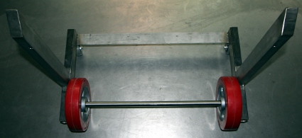
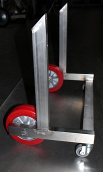
Wheels:
- Frontwheels: Bickle, 200 mm x 50 mm. Axis: 20 mm, axis hole depth: 60
mm. Red polyurethane tires.
- Backwheel: Rotating wheels, building heigth 80 mm. Mounting bolt M12.
Grey tires.
Lightbulbs used:
Frontlight: Halogen 10W 6V, Radium Skylight type nr. RJ1006, GY4 2-pin socket
(mapped on note 120)
- Sidelights: LED Osram assemblies, 12V (not user controllable)
- Tungsten light on chassis: 6V, E14 socket (mapped op note 121)
- Red lights: two units with each 3 1W red LED's, powered from 6V dc. (mapped
on notes 122 and 123).
- Halogen light on the frontal part of the chassis: 6V, 4.2W E10 socket. (mapped
on note 124).
-
Download high resolution pictures of this robot: [not yet available]
Criticism:
- Although the bidirectional solenoids used for the first prototype work here,
their force is still way too low for a powerfull plucked-string sound. Thus
the velocity range possible with <Zi> using this mechanism is far below
our initial expectations. Hence the construction of a second mechanism, using
bidirectional bipolar solenoids. The clicking noise these solenoids produce
seems to be unavoidable.
- The second mechanism proved unworkable as well and was rejected again. In
2024 we started a new experiment using linear motors.
- Linear motors do work, but due to their delays the timing becomes completely
unreliable, hence musically unacceptable...
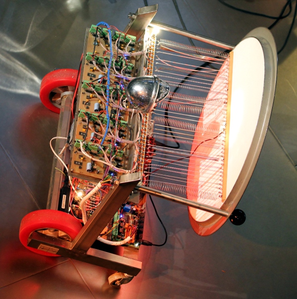
- The styrofoam soundboard performs very well. Thus, for version 3 -<Zip>
- we made a new round styrofoam resonator board. Diameter 640 mm.
-
References:
Linear Technologies: LT1083,
LT1084, LT1085 Low dropout positive fixed voltage regulators
Microchip
PIC 18F2525 manual
RAES, Godfried-Willem, "Expression
control in musical automates", 1977/2026
SMIT, Thorsten a.o.,
'A highly accurate plucking mechanism for acoustical measurements of stringed
instruments', in: Journal of the Acoustical Society of America, EL223,
may 2010.
STMicroelectronics: Data
sheet for the L298 dual full bridge driver
STMicroelectronics: L6201-L6202-L6203
DMOS dual full bridge driver
Syndyne catalogue

Archival: Rejected version 1.0 documentation:
see Zi.html