Dr.Godfried-Willem RAES
Kursus Experimentele Muziek: Boekdeel 2: Live electronics
Hogeschool Gent : Departement Muziek & Drama
| <Terug naar inhoudstafel kursus> | MOTORS | Dit hoofdstukje is niet beschikbaar in het nederlands. |
2113:
Application
<Controlling the speed of 3 phase induction motors>
The speed of a normal 3-phase induction motor is a function of the frequency of the supply voltage. Changing the speed of such a motor hence requires building a 3-phase power frequency convertor. The driver can be realised using power mosfets (or IGTB's) capable of handling high voltages and fast switching speeds. The generated frequency can be programmed in a small PIC controller and even in a fast Basic Stamp.
Note that at lower than normal frequencies, the voltage should be decreased proportionally. If you forget this, the motor may overheat and eventually even burn out. (See note at the bottom of this paragraph). The circuits shown here serve mere educational purposes (although they do work!) and are not always the most suitable nor safest sollution.
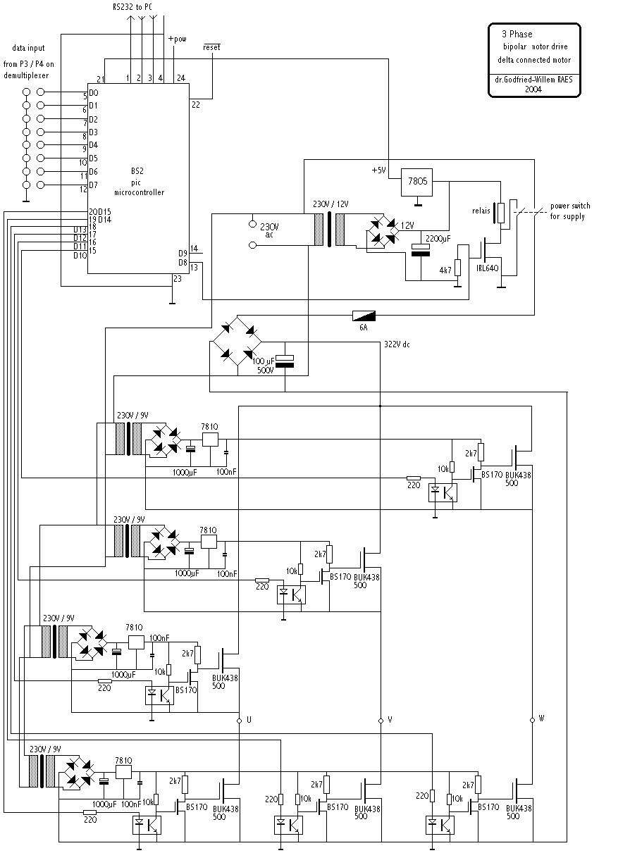
For the bipolar drive circuit shown below, the motor should be delta-connected.

The optocouplers used can be either TIL111 or CNY17-2. Do not try to save on the transformers: these are very small and cheap types (2VA is enough) and the floating way they are connected here (no grounded negative poles!) is essential to this design. Be carefull when playing around with this kind of circuitry, since there are high voltages everywhere. The digital input and the microcontroller are completely and optically isolated from the power circuitry.
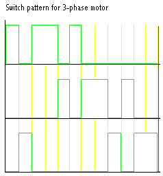
The bit-pattern to be programmed in the controller software could look like:

Note the 120 degree phase shift. The pattern was designed to generate a lot of thirth harmonic distortion on the resulting wave, thus increasing the RMS voltage over the motor windings.
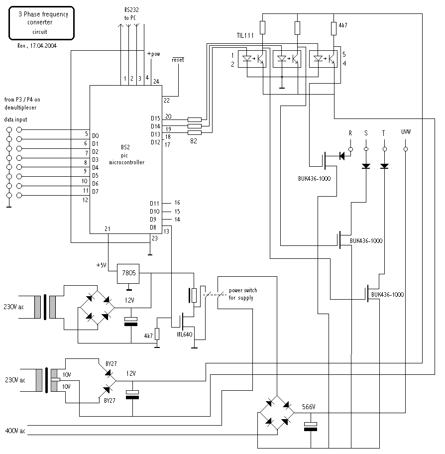
If you want the motor to be Y-connected, the problem will be that you need a much higher voltage to work from. Using a 3-phase rectifier bridge, you can of course use rectified 3-phase mains current, but that presupposes its availability. Ass an alternative an insulation transformer 230V/ 400V can be used. However, at the end this will tend to be more expensive than the circuit given above. The circuit below however will become a lot simpler, since we do not require 6 mosfets and no floating powers supplies:

Applications:
NOTE:
If you are in need of a controller for a 3-phase motor, you should always consider using one of the many modules the industry offers these days. Factories such as Lust gmbh, Siemens (Micromaster 410), Toshiba, Hitachi... all have controll modules in their catalogues. Controlling the speed of the motor using such a standard solution can be done by sending an analog voltage (0-10V most of the time) to the appropriate input, or, on some models, by sending RS232 commands to their port. The advantage of these modules is, amongst other things, that they serve as a motor protector at the same time. Also, it might at the end be cheaper than building the circuits shown above yourself.
Prices range from 300Euro to 600Euro, depending on required power and features.
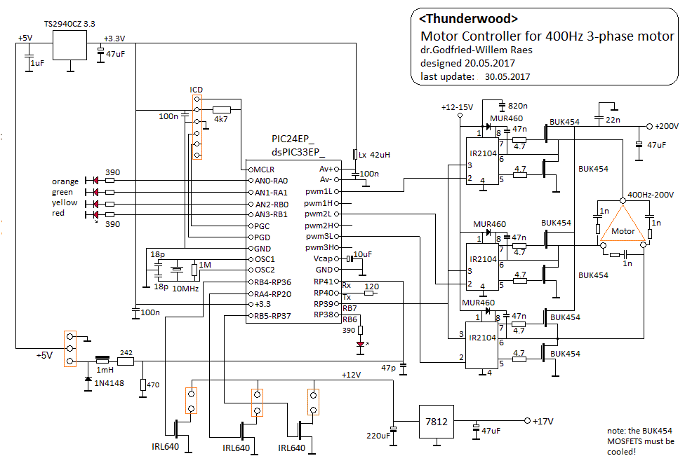
For very specific motor types, it can still be fruitful to design a specific motor controller. This is what we did for our <Thunderwood> robot, where a 400 Hz / 200 V motor was used to drive the storm-wind mechanism with a small radial compressor. These are common specifications for motors designed to run on airplanes. The controller uses a 16 bit PIC microprocessor (type 24EP128MO202), as this type has 3 independent PWM outputs (6 outputs even, in complimentary mode). Here is a tested circuit:
 If you want to have a look at the source code for the firmware in this circuit,
visit the <Thunderwood> page
on our website. It has all technical detains, a diary as well as links to the
code.
last update: 2017-05-27
| Terug naar inhoudstafel kursus: <Index Kursus> | Naar homepage dr.Godfried-Willem RAES | Deze pagina is niet beschikbaar in het nederlands |