|
< Vibi >
an automated vibraphone |
|
Godfried-Willem RAES 2001 / 2005 |
|
< Vibi >
an automated vibraphone |
|
Godfried-Willem RAES 2001 / 2005 |
Most certainly, we are not the first to have automated the vibraphone. We recall very well the extensive work done in this field by our friends -at that time in Baltimore- Carney and Alec Bernstein. But sure enough, many more instrument builders have undertaken this task before. Of course we are not forgetting the many pneumatic implementations found in the large dance organs (orchestrions) from the interbellum (Decap, Limonaire....) of vibraphones, xylophones, glockenspiel etc..., although these were pneumatic and pretty primitive, lacking fine dynamic control. So, when we started our own attempt to realize an automated vibraphone, we could build further on these experiences and take off from there.
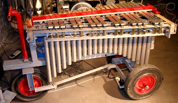
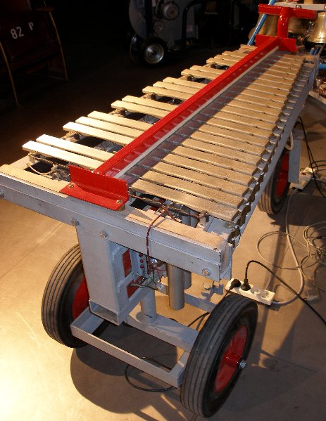
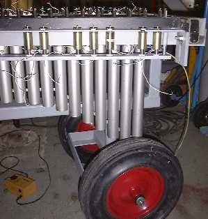
Our own design had to become a computer controlled acoustic vibraphone with touch controll and individual dampers for each bar. The starting point for the practical construction was an small model Yamaha vibraphone (type YV-600B, serial number 1977) ) of which we only kept the tuned aluminium staves and the resonators. The original global damping mechanism (activated by the pedal) was thrown out altogether. A new electric circuit was designed for the vibrato mechanism, since the original one was too noisy and could not be easily computer controlled.
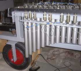
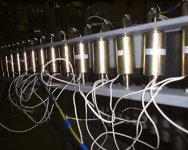
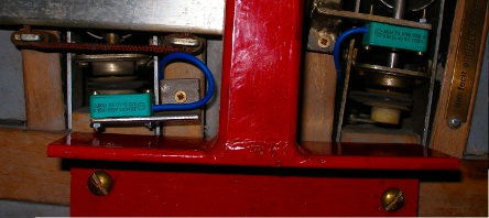
The beaters make use of Lukas Ledex solenoids (similar as the one we used for our player pianos), mounted under the extremities of the sound bars. The dampers were made with the same type of solenoids, but here we mounted rubber or felt pads on the anchors as dampers. No springs were used. The anchors falling back on a heavy felt covered steel bar by gravity alone. The design started off with an analysis of pulse timing requirements for the automated vibraphone:
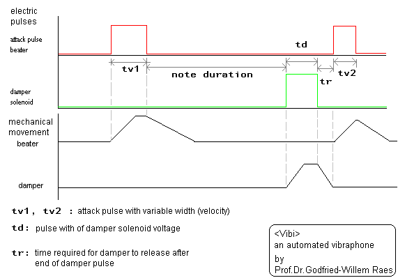
The attack pulse tv1.tv2... (for power supply voltage of 44V -see further) should range between 3ms and 15ms. If we want good dynamic controll, it is enough to controll precisely the pulse width of the attack solenoids with the beaters. The pulse duration for the dampers (td) could be constant and, if so, equal to the minimum pulsewidth required to damp the bar (ca. 50ms) . At rest, the damper can be released, so no power is spoiled. The maximum repetition speed will be dependent on the dynamic used and is limited anyhow by the time required for the beater to fall back plus the time for the damper and the time for this damper to fall back. Of course, when playing very fast repeated notes one could decide not to use the dampers. But even than, the repetition rate will be determined by the time it takes the beater to fall back. If we mount the anchors with springs, the fall back time can be decreased, but only at the detriment of dynamic range: the heigth of the (compressed) spring should be subtracted from the original movement traject. Also springs unavoidably introduce their own resonant frequency, interfering with some repetition rates.
This design offers many more musical perspectives than either what musician playing vibes could have to offer. First, it is truly polyphonic with complete autonomy for the individual beaters. So no longer a limitation to 2 ,4 or if conservatory acrobatics are used, 6 notes/sticks. Second, as we provided individual dampers for each bar, the musical possibilities in terms of expressive refinement are greatly enhanced. Third, since we finally decided to also implement velocity for the dampers, we can control the damping up to the smallest detail. This way even the most 'avant-garde' playing techniques can be realized on this automat. What we have not implemented is changes of sticks, as musicians are often required to do in typical contemporary music pieces. This would have required at least yet another row of solenoids with softer beaters. There is barely enough space under the bars to allow for such an untertaking. Of course we could place them above the bars, but then one potential element of magic in the instrument would disappear: the possibility of manualy playing the instrument at the same time as its automat plays. Nevertheless it requires the user only to exchange all 37 beatercaps if it is realy required to sound this vibraphone with a softer (or harder) attack.
A new element in the design of this robotic instrument is that we implemented a damper-hold mode, whereby the felt covered dampers can be pushed against the staves with a continuously variable force. Thus the staves can also be played whilst damped to a variable degree. It was easy to implement this since 8254 type timer chips can be programmed to operate either as programmable one-shots or as square wave generators. In the latter case, since their outputs drive the solenoids via mosfets, we take profit of the fact that the coils impedance rises with the frequency of the applied voltage. Thus the current through the solenoids can be controlled by programming the periodic frequency of the timer chips. At some operating frequencies in the audio band however, this operational mode can lead to audible noise stemming from the solenoid anchors. This possibility however is only available when controlling <Vibi> with a laptop of its own. The midi-input version has nu support for this operational mode.
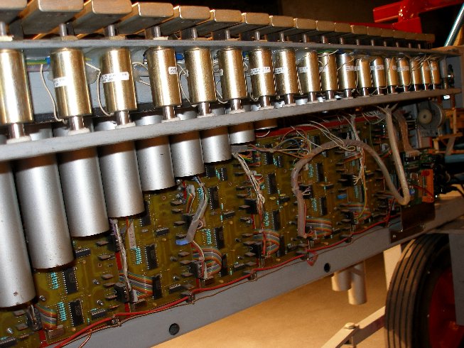
As usual in our instrument designs, we constructed TIG welded steel frames for the entire magnet and electromechanics assembly. Bolts on the sides of the instrument in combination with the bolts holding the fallback bars under the solenoids, allow for fine adjustment of the traject of movement for the beater and the dampers. This affects the dynamic range. The instrument was mounted on large and very sturdy wheels of the same type as used in most of our other robots that make up the Logos <M&M> ensemble.
The note range of the instrument is 37 notes, 60 to 96(C-c") expressed in midi notes.
For the electronic control of this instrument we used our own <GMT> software in combination with the hardware we designed for player pianos. Thus the instrument is played using a Wintel Pentium PC. Of course the instrument can also play standard midi files. The demultiplexer for the parallel input coming either from a midi PIC board, a standard printer port, an ActiveWire USB interface, or a National Instruments DIO-24 or 6533 device, looks like:
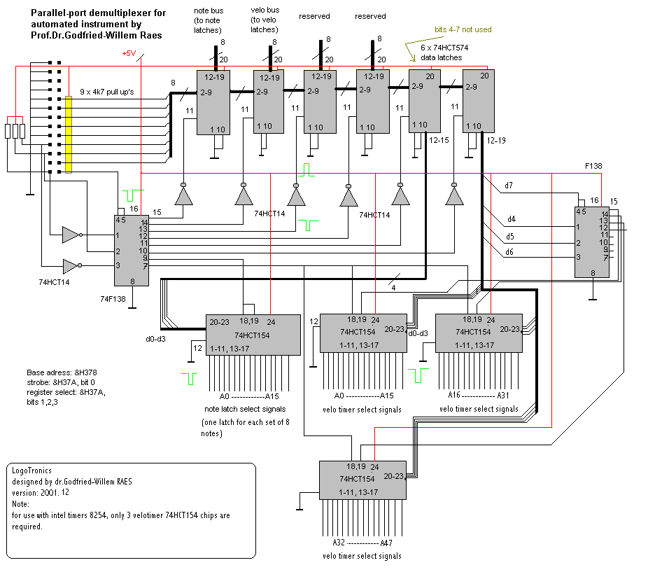
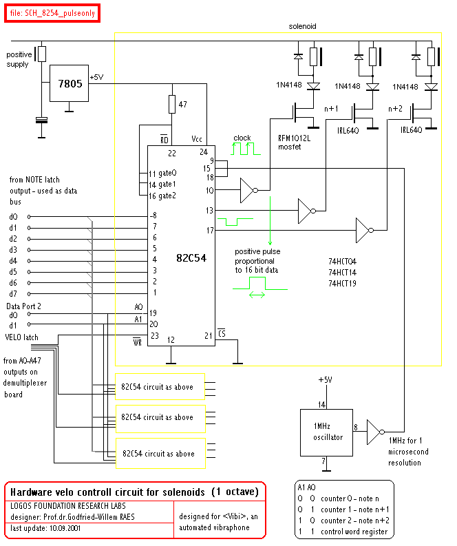
The note driver board and the velocity controll circuitry was build after following schematics, using intel 82C54 programmable timer chips, used as programmable one shots in this application. The pulse width, using a 1MHz clock, is programmable between 1 microsecond and 64ms. The practical (and musically relevant) range used and set in the software is 3.5ms to 16 ms. We use the following formula for the rescaling of midi velo values into microseconds: pulse = 2048 + (velo * 128/4) + (velo^2 / 4). The dampers use a different mapping.
bus-demultiplexer PC board lay out
(These PC boards -without components- can be obtained against
cost from the author. One board accomodates one octave. Delivery time does not
exceed 2 weeks. Prepayment is required. Inquire by email if interested. Tested
boards with components costed ca. 260 Euro's a piece. 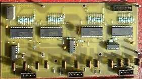
The solenoids used are: Ledex STA series push tubular solenoid type nr. 195207-228. They have a cold DC resistance of 19.1 Ohm. The nominal working voltage, at which the coils can be activated indefinitly long is 13.8V. At 10% duty cycle, a voltage of 44V may be applied.
motor board:
The resonators, as usual on a vibraphone, have a rotating mechanism allowing them to be periodically opened and closed. Each row of resonators has its own rotating shaft. So we provided 2 stepping motors, such that rotational speed of upper row and lower row can be controlled independently over a wide range. To achieve this we used the two 8-bit auxiliary ports on our demultiplexer board to controll two PIC microcontrollers. Thus the software could suffice by sending a byte (0-255) to control the rotation speed of the motors. The code, microcontroller basic, for the PIC's can be found in our Stamp directory. The circuit we developed for these controllers is quite simple:
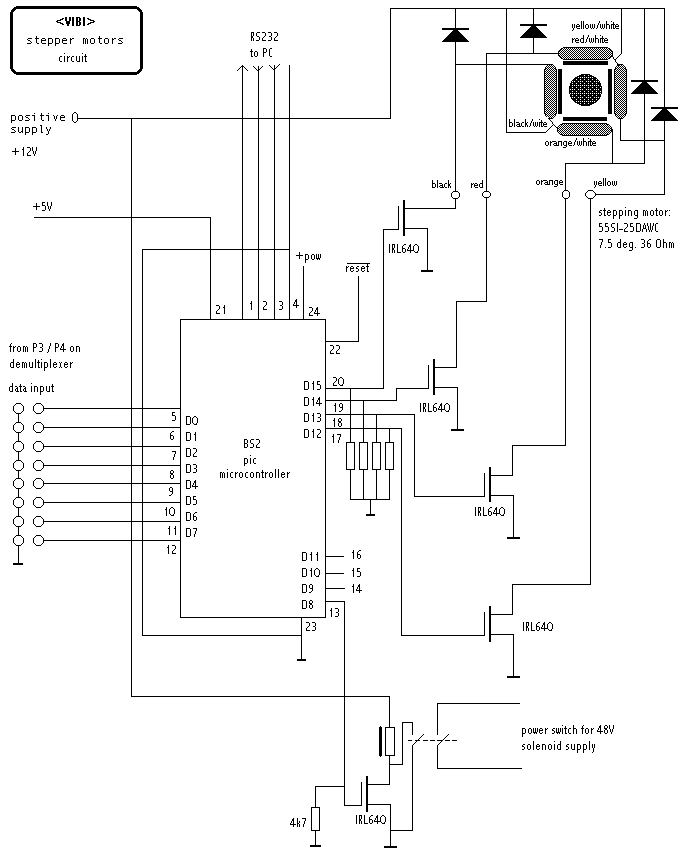 The Basic
stamp used here is a BS2p24 type, clocked at 20MHz. It uses a scenix SX48AC
controller.
The Basic
stamp used here is a BS2p24 type, clocked at 20MHz. It uses a scenix SX48AC
controller.
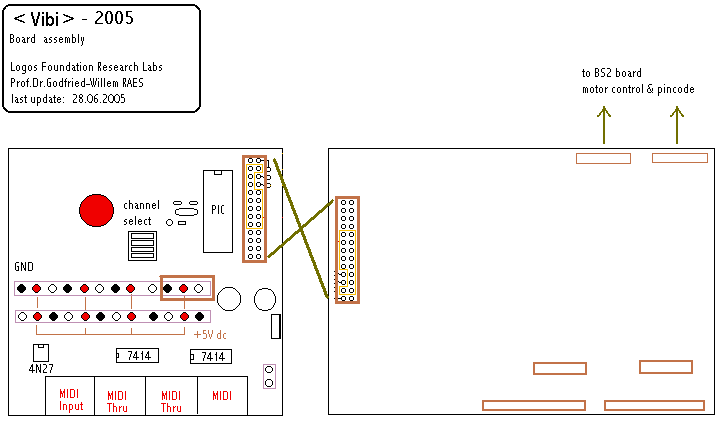
An overview of the final assembly of all circuit boards used for <Vibi>, looks like:
The wiring of the PIC-board translating midi-input to our parallel bus looks like:
[comments on these circuits, first developed for one of our player pianos can be found at/kursus/2116.html.]
<Vibi> has played at following venues/occasions: Tourcoing (France, Le Grand Mix), Ghent (Logos Tetrahedron), Amsterdam (Paradiso), Herne (Germany, Teutoburgia Halle), KULAK University (Kortrijk), Yttre (Wallonia), TART symposium (Enschede), Festival in de Branding (Den Haag), Adventures Festival (Korzo Theater, Den Haag), Lille 2004 (Aeroneff, Lille), Muenchen 2005, DeAvantgarde Festival (Muenchen), November Music (Den Bosch), Computed Music IV (Koeln), Jauna Muzika Festival (Vilnius, 2007), Orgelpark (Amsterdam, 2008), Dag van de Oude Muziek (Alden Biesen, 2010), STAM-opening (Ghent, 2010)...
Available repertoire for <Vibi>, alone or in combination with other automats.
|
Tech-Specs -----------------------------------------------Technische specifikaties: Aanvang bouw: augustus 2001 - . <Vibi> speelde zijn eerste toonladder op 9 oktober 2001 en was volledig afgewerkt op 16 oktober 2001. Het materiaal van de aanslagkapjes werd vernieuwd in 2004. In 2005 werd <Vibi> omgebouwd zodat hij ook zonder laptop besturingskomputer rechtstreeks midi signalen kan verwerken. Het vibrato mechanisme werd helemaal herzien in 2010. Size-----------------------------------------------------------------------------------------------------------Afmetingen van het afgewerkte instrument:
Power--------------------------------------------------------------------------------------------------------Stroomvoorziening:
Insurance value (for organisors):
Rental / concerts:
|
|
Midi Implementatie: The default midi channel for <Vibi> is set to 11 (if counting channels from 1, otherwize, 10)
|
| Godfried-Willem Raes | <A Last Repetitive>, 1976 | for naked dancer and vibraphone |
| Godfried-Willem Raes | <Vibes for Vibi>, 2001 |
solo composition - environmental music, with optional <Harma> and <Piperola> part. (Premiered on the Polymachina festival, Tourcoing, 2001) Available on CD: LPD008 |
| <Trio Paradiso> | for <Vibi>,<Klung> and <Harma> (Commisioned by Paul Koek, premiered at Paradiso Amnsterdam, 12.11.2001) [5'00"] | |
| <Paradiso> |
for <Vibi>,<Klung>,<Player Piano>,<Harma>,<Piperola> and optional musicians [10'30""] Available on CD: LPD008 |
|
| <Eary Lis Trimbl> |
for automat orchestra, a naked singer and optional musicians [10-15'], 2002 Available on CD: LPD008 |
|
| <Lithos> | for complete automat orchestra, including <Vibi>. Act1 of Technofaustus. | |
| <GeroVibi> | for invisible instrument and a naked player | |
| <Tekne> | for complete automat orchestra, including <Vibi>, from Technofaustus (mefistodance) | |
| Eric Satie | Ogives | |
| Howard Skempton | <Pendulum> | |
| John Cage | ||
| Barbara Buchoviec | <Moonflower> | for vibi solo LPD012 |
| Kristof Lauwers | <Generic Sonatas> |
for automat orchestra, 2002 Available on CD: LPD008 |
| Sebastian Bradt |
<And they...> |
for automat orchestra |
| <Zurge> | for automat orchestra | |
| <Everything> | for automat orchestra | |
| Kristof Lauwers | <Plastic Deformations> | for automat orchestra (percussion robots only). Available on CD: LPD014 |
| Xavier Verhelst | <SillyVester> | for automat orchestra |
| Sebastian Bradt | "Treefingers" | for vibi, harma, piperola, bourdonola. Available on CD: LPD013 |
| Godfried-Willem Raes | "SQE v STO 4 QR" | for percussion robots. Available on CD; LPD014 (Robodies) |
| (Terug) naar logos-projekten: projects.html
Back to logos projects |
Terug naar Logos' index-pagina
back to main index |
Naar Godfried-Willem Raes personal homepage...
back to Godfried's page |
Naar katalogus instrumenten
gebouwd door Godfried-Willem Raes
back to catalogue of instruments by Godfried-Willem Raes |
 |
Construction assistants for <Vibi>:
Service manual & detailed circuit and maintenance documentation
Following information and documentation is not intended for the general public. It is provided as technical documentation for our maintenance staff at Logos Foundation.
Setting <Vibi> up:
Switching <Vibi> on:
When the power is switched on, the 5V (all logic circuits and PIC controllers) and 12V (stepping motors) power supply will start. Then one of the microcontrollers will wait for the reception of a pincode (251) from the computer (GMT software) and only if a match is found, the 48V power supply will be switched on. The PIC controller switches a relay on, causing the AC supply to the 48V SMPS to switch on. To reset, all power has to be switched off . The second PIC controller -loaded with identical code, switches the small 'Logos' display on, located at the high note end on the multiplexerboard side of the circuit board assembly. So, remember to always first switch on <Vibi>, and than start the PC's application. If the direct midi-in board is installed, the power up sequence will be automatic and only rarely the users will have to send the PIN-code via the midicontroller implemented to this purpose (controller nr. 66). Anyhow, it does no harm to always send controller 66 with value 1 at the start of midi files or tracks for vibi.
Circuit boards overview:
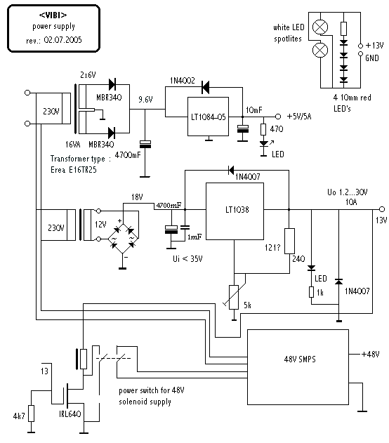
There are 2 power supply systems: the first one - housed in a black metal cage- gives 5V and 12Volt voltages, the second one only the 44V for the solenoids.
The first power supply is a caged SMPS rated at +5V/15A and +12V/2.5A. It is mounted on the left side of the circuit boards assembly plate, next to the velopulse boards. The -5V/1A is not used in our application. A 110/220V primary switch is provided on the board. There is a 1W 560Ohm resistor between the +5 and ground. This is the minimum load required for operation. Do not remove this resistor. The +5V can be trimmed with the potmeter. Adjust it with all load connected to exactly 5.00V. The +12V output is only used to power the two stepping motors on the instrument as well as the relais circuit to activate the second power supply, such that this voltage comes up only after reception of the appropriate pincode through the GMT software. As a consequence, whenever the power is cut on the instrument, users will have to bootup again (quit and restart GMT with the vibi application, or power down completely and restart, if the midi-in board is installed).
All solenoids have a common positive voltage connection, connected to the second power supply. This power supply is mounted on the right side of the circuit boards assembly, where also the demultiplexer board and the stepping motor boards can be located. The second wires come together in Weidmueller 4-pole connectors (three for each board covering an octave) to the note hold and velo boards.
The positive voltage can be adjusted on the second power supply printed circuit board with the multiturn trimmer. The voltage should be adjusted such that when the shortest velocity pulses are applied, the solenoids develop just enough force to barely hit the bars. Initially we found 44V to be a suitable setting. This is the highest voltage allowed for a duty cycle of 10%. When testing software, it is best to temporarily use a lower voltage (say 24V) power supply to avoid burning out the coils due to software errors and code bugs.
There are 8 timer boards (each covering an octave) on the mounting plate. The last board on the bus (the note board for notes 0-11), has Shottky termination diodes (BAT45) mounted between ground and +5 over the data lines as well as over the A0,A1 adress lines for the timers.
Although the midi mapping is on notes 60-97, the hardware as well as the corresponding low level driver code in the PIC or in our DLL (g_n*h.dll), remaps this into 'hardwire' notes 0 to 37 (for the beaters) and 48-85 (for the dampers). The beaters use the strobe signals generated by the first velo 74154 demultiplexer, whereas the dampers use the second chip. The third chip on the demultiplexer board is not used in this application. All strobe signals are negative pulses, minimum 1 µs, maximum about 12 µs in length. Thus the use of long interconnecting cables is possible (although, not advisible).
Maintenance logbook:
15.01.2005: Input circuit modified such that Vibi now takes midi commands directly,
using a PIC controller.
28.06.2005: 5V/12V SMPS removed and replaced with 2 analog power supplies. Midi
in series resistor (was 220 Ohms) reduced to 133 Ohm by parallelling the existing
value with an 330 Ohm resistor. This improved the quality of the midi signals
considerably. Optocoupler is 4N27, mounted on the PIC board.
01.07.2005: White LED spotlights added on backside. 4 large red LED's as well.
Documentation updated.
25.04.2007: Vibi damaged after transport to Vilnius. Repaired locally: note
board 60-71, 5V power supply connector broken off because resonator tubes jumping
out of their holders in transportation. Vibi returned from Vilnius on may 2nd.
10.01.2009: The modulation wheel motors need a replacement...
13.10.2009: Belt for diatonic vibrato motor replaced.
10.05.2010: Note 82, damper solenoid burned out and mosfet gone... repair required.
10.06.2010: All beater caps replaced with new ones.
09-10.10.2010: Vibi plays on the opening of the STAM museum on the Bijloke campus:
12700 visitors...
10.11.2010: Start of a redesign of the motor mechanism, associated electronics
and firmware. We want to add sensors to the tremolo mechanism such that we can
stop the motor in a position with the resonators fully opened.
13.11.2010: Construction and mounting of a Pepperl+Fuchs position sensor for
the chromatic resonator motor mechanism. The diatonic side was more of a problem
due to the severe space constraints. Here we mounted the sensor anchor on the
holding bolt of the drive wheel. A small offset to the full opened position
thus became unavoidable and had to be remedied in the PIC firmware. With the
new hardware, it will be possible to add lights to <Vibi>.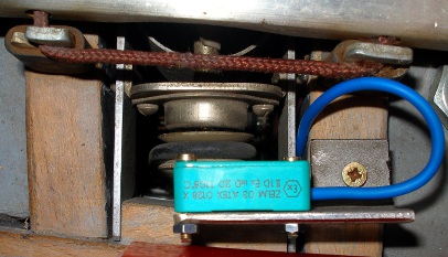
 The placement
of the sensors can be seen in the pictures. The sensors are mounted with M2.5
bolts and nuts.
The placement
of the sensors can be seen in the pictures. The sensors are mounted with M2.5
bolts and nuts.
14.11.2010: Physical design... trying to make space for the new hardware...
19.11.2010: New pic controller board breadboarded. Two controllers, 18F2520
are used.
20.11.2010: Yellow LED strip mounted behind the frontal resonators. Two Nanotech
motor controllers mounted. Breadboard circuit with two PIC microcontrollers
finalized. Start coding for the firmware. This webpage made archival. No longer
updated.
Last update: 2010-11-20 by Godfried-Willem Raes