<BumbleBee>
a cheap radar based gesture controlled instrument
by
dr.Godfried-Willem Raes
post-doctoral
researcher
Ghent University College & Logos Foundation
2009
Bumblebee is a microwave radar based installation for capturing information on human body movement to be used for embodiment research, controlling automated musical instruments and robots. Of course the equipment can also be used as a controller for midi devices such as synthesizers or audio effect processors, as well as for real time audio processing. In these functions it contitutes a cheap alternative for our earlier sonar and radar based invisible instruments. With this setup, it is possible to retrieve absolute information about the 3-dimensional position of a player as well as about the size and aspect of the surface of the moving body. Also absolute movement velocity and acceleration can be derived as parameters. The system is inherently wireless and as such it enables the realization of an invisible instrument.
This article presents the hardware, comments on its design, the software implementation as well as it discusses some artistic applications. The equipment is available at the Logos Foundation in Ghent (2). It is open to composers, performers and scientists for experiment and development of productions.
Hardware
In the Logos lab a very wide range of different radar devices have been
and are further being researched operating in different frequency bands: 1.2GHz,
2.45Ghz (our Quadrada System), 9.35GHz (our PicRadar system), 10.58GHz, 12GHz,
24GHz (our Tetrada system), 77GHz. This report reflects our findings and realisations
using a board-based pulsed doppler radar device operating in the 5.86GHz band
costing only $100 a piece at www.samraksh.com.
The hardware side of this installation consists of the following electronic
components:
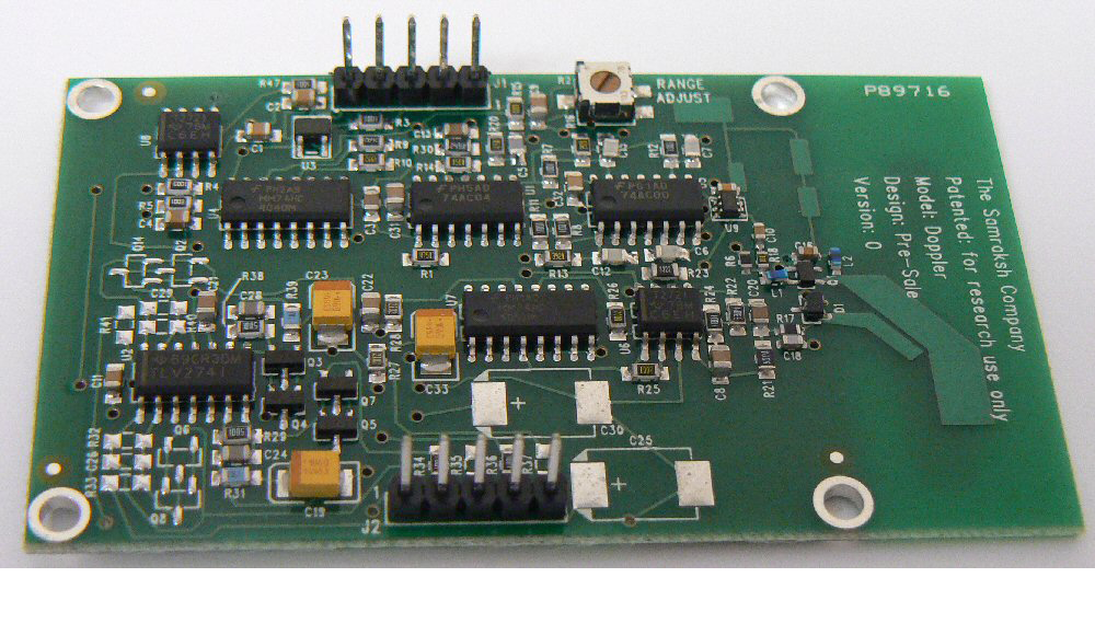
1. four microwave radar devices.
These boards measure 7.62cm x 4.45cm, the radiating antenna -integrated on the board, being located on the right side. The radiation angle of the antenna is 60 degrees.
Their operating frequency is specified at 5.86GHz. The emitted electromagnetic waves are reflected by reflective surfaces and if in movement, these will cause a Doppler shift between emitted and reflected signal. As to human bodies, the most reflective surface is the naked skin. We performed measurements showing that a pullover gives a damping in the order of at least 12dB, thus reducing the resolution of the interface effectively with a factor 4 or worse. Hence our advise to always perform naked with any version of this invisible instrument. Within the context of our own compositions, we make this nudity even compulsary.
Doppler formula:
fd = 2 v fo / c
so, after solving the device specific constants we get:
fd = 39 v
This holds for movements in line with the axis of the sensor. For other angles, the formula becomes:
fd = 39 v cos(a)
Where a is the angle between the movement and the axis of the sensor. The circuit is optimised for the movement velocity range between 2.6cm/s and 2.6m/s
When we sample the signals at 256 S/s, the highest detectable frequency would be 128Hz, conforming to the Nyquist theorem. So this limits the maximum detectable movement speed to
v = 128Hz / 39 or ca. 3.2m/s.
So if we wanted to be capable to resolve movement with higher speeds, we would have to increase the sampling rate accordingly. Note however that moving human bodies rarely exceed speeds of 5m/s. Therefore sampling rates much higher than 512S/s do not lead to any gain in information particularly since the board used has pretty sharp low pass filters.
Signal amplitudes are inverse proportional to the square of the distance to the antenna and directly proportional to the size of the reflective surface of the moving body. The detection range for these devices is variable from 1 to 10 meters. Noise limits the range of the unit. Since we want the device to operate in real time, there is no way to resolve signals below or around the inherent noise level of the devices. The polar sensitivity, according to the datasheet, shows an opening angle of 60° in a conical shape. This almost dictates an application with four devices set up on the vertexes of an imaginary tetrahedron.
The devices each output two signals. The phase between them allows us to determine weather a body is approaching the antenna, or moving away from it. We can consider these signals as the two components of an imaginary number I,Q where I is the real part and Q the quadrature or imaginary part of the signal. The amplitude of the signal (proportional to the size of the reflecting and moving surface) than equals I^2 + Q^2.
The I and Q outputs from the board have a voltage range of 3.2Vpp. The noise level is at 30mV, thus yielding a dynamic range of 30dB. The switching pulses from the microwave emitter can also be found back in the output signals, so an low pass filter in the software can be required for optimum performance. In order to adapt the output signals of the board to the optimum range for our ADC devices (National Instruments NI-USB6210, 16 channels, 250kS/s, 16 bit), we build a simple opamp circuit giving a gain of just 3 and a little bit of low pass filtering.
2. Adapter board This board also houses a linear stabilized power supply for the transducerboards. These require anything between 5V and 15V dc and draw about 40mA each. This brings the total power requirements, including some safety margin to 9V/ 200mA, or no more than 1.8Watt. Standard 5pole 180° DIN connector cabling is used for the interconnections. Pin 1= +15V, pin 3 = -15V, pin 2 = ground, pin 4 = I-output, pin 5 = Q-output. Pinning and wiring is compatible with the 24GHz microwave setup described in another application note.
As we noted in earlier publications based on our research into microwave radar devices (1), the sensors used here can also be disturbed by ionising sources in their neighbourhood and range of sight. When using the 10 to 30GHz range, the effects of gasdischarge lights often made the use of the equipment problematic. With the sensors presented here, operating on the much lower frequency of 5.86GHz, this source of noise is strongly reduced but still exists. So the use of this equipment together with CRT's, TV-sets, TL-light, mercury vapor bulbs, our own digital loudspeakers, welding equipment, sodium vapor bulbs within a range of 10 meters around the setup should be discouraged. Another consideration is worth mentioning: the boards should be placed at least a full wavelength (ca. 5.2cm, for these devices) away from any grounded object, since the presence of such objects sucks away all radiated energy from the antennas.
Software
The software consists of two levels: a first level, a thread in its own, samples the signals from the transducers at the required sampling rate and processes this data such that we get access to following parameters:
To this end, a number of different algorithms are available for calculating this data set:
The inherent problem with the first two types of signal analysis -in this respect it is no different that what we stated with regard to ultrasonic technology in earlier reports- is that the signals do not typically show up really periodic components. The most relevant information is in the amount of deviation from periodicity. Acquiring this kind of information using FFT is generally speaking, not the best solution. Therefore we provided some alternatives as described above.
The musically most usefull results we got from using an algorithm counting the number of signal direction changes, larger than the noise level set, over the last second or less of data in the buffer. The default sampling rate, corresponding to the most useful setting after our experiments, is 256S/s. As to the derivation of most relevant information with regard to the amount of body surface moved, we found calculation of the root mean square of the most recent 500ms of the databuffer contents an optimum setting. We rescale the obtained value by taking its log2 value and multiplying it by 11.54. Thus we obtain a 'midi-compatible' 7-bit dynamic value directly.
The relevant procedures, including many more features than we can describe here, are integrated in our DLL library g_nih.dll. The source code is available. The required exported functions are:
GetRadarPointer (devicenumber) AS DWORD
this returns a pointer to the structure defined for each transducer. This structure behaves like an object and sets and returns all relevant data, operational mode and parameters. Devices are numbered 0 to 3.
The structure is defined in g_type.bi as:
TYPE RadarType DWORD alignment on dword boundaries pxbuf AS INTEGER PTR contains a pointer to the zero'th element of the databuffer (0 to 255) for the x-phase signal of a single sensor pybuf AS INTEGER PTR idem for the y-phase xa AS DWORD 11.54 times Log2 of the RMS amplitude, so the range is 0-127. The timewindow is 250ms. ya AS DWORD same for the y phase signal xal AS DWORD 11 bit amplitude value, over the last detected complete doppler period encountered in the x-phase signal yal AS DWORD idem, y-phase l AS SINGLE normalized distance based on the integrated rms signals from the x and y phase of a couple of transducers. Range 0-1 s AS SINGLE size of absolute surface of moving body as seen by the transducer v AS SINGLE absolute speed of slow (center of gravity) displacement of body acc AS SINGLE acceleration value of the above parameter pc AS COMPLEX cartesian coordinates of absolute position (0,0 = center of the setup) pl AS POLAR the same in polar coordinates xt AS SINGLE period of last x-phase doppler signal for internal use yt AS SINGLE period of last y-phase doppler signal for internal use xf AS SINGLE doppler frequency x-phase, not corrected with cosine of movement angle for internal use yf AS SINGLE idem. for y-phase for internal use vf AS SINGLE absolute value of fast movement speed based on the doppler shift frequencies received and with the cosine factor applied (in Hz) for conversion to physical units m/s you have to divide this value by 16.3. The range is 0.5 to 64Hz.(90Hz with cosine correction, but such values are unreliable) acf AS SINGLE absolute value of fast accelleration phase AS SINGLE phase angle between x and y phase signals for internal use noise AS LONG noise floor. Can be set by the user. can be set by the user dT AS DWORD Size of the time integration window, expressed in number of samples. Good values are between 16 and 80. The default is 64. can be set by the user params AS DWORD sets the algorithm for doppler frequency determination. Used with the declared constants: %ISOLWAVE, %DFT, %ZEROCROSS, %SIGNCHANGE, %ISOLPERIOD numeric values for these constants are in g_kons.bi setup AS DWORD sets the physical setup used for the radar transducers. Used with the declared constants:%SQUARE, %TETRAHEDRON, %FREE, %CUBE numeric values for these constants are in g_kons.bi END TYPE
In the software implementation we start by declaring an array of 5 variables of this type: r(0) to r(4), the last one just for holding global information on the detected movement from all transducers combined.
Radar_DAQ (param) AS LONG
this procedure starts / stops data acquisition from the connected transducers.
Declarations for these functions can be found in the file g_h.bi. Of course users do have to install the proper drivers for the DAQ card used (NiDAQmx software from National Instruments). This software comes included with the purchase of any such device from National Instruments.
To derive musical meter and/or tempo information from the data acquired, one should apply a low pass filter with cutoff at 4Hz and store the buffered data in a memory array. A DFT performed on such a buffer with a data depth of 8 seconds will reveal gestural periodicity -if present- pretty well.
The derivation of meaningful information with regard to the gesture input is based on the same considerations and gesture typology as described in "Gesture controlled virtual musical instrument" (1999), with this difference, that the setup of the transducers in the form of a tetrahedron is not mandatory here. Of course, for the math involved to work well, one has to stick to the setup requirements and conditions implemented in the software.(4)
This way the values returned in our structure , in the .vf field, are obtained. Since there is a fourfold redundancy, the found values can be averaged to reduce noise and inherent movement uncertainty. (5) If the signal amplitudes are high enough above the noise level, we can also derive relevant information with regard to the change of shape in time of the moving body. This can be very significant for dance movement analysis.
For a tetrahedral setup, the math involved is different and more complicated than it is for a square set up as done in Quadrada, but pretty straigthforward as well. It has the advantage that we can derive full 3-dimensional positional information. Moreover, the uncertainty of the resulting values is much lower in this setup, since the angles all are one third smaller.
The data acquisition card we use has a 16 bit resolution. Since the normal noise level of the system is around 30mV, and the ADC inputs are configured for a bipolar range of -5 to +5V, whereas the peak-to-peak values of the signals are limited to 3.2V, we should consider the last 5 bits as irrelevant. The practical resolution, and therefore the precision of the system, cannot be better than 8 bits, corresponding to a 40dB dynamic range.
Artistic applications
The <BumbleBee> suite is a collection of studies -under development- in which we try to explore different ways of mapping gesture information on musical activity produced by our robot orchestra, composed of following robots:
All the studies in this series, and
in fact all compositions by the author making use of any version of the invisible
instrument, have to be performed naked.
The equipment is available for any competent composer wanting to develop a piece or performance using it. Since the use of the instruments requires software to be written, it is highly advisible to study our <GMT> software and its functionality with regard to this instrument. It is possible to use the equipment with other data acquisition systems, provided they can handle 8 channels, have at least 10 bit resolution and a reasonably fast sampling rate.
Other compositions by the author making extensive use of this equipment are "Transitrance", "Technofaustus" and "SQE-STO-4QR". In 2007 we used the Quadrada microwave devices in a hybrid gesture sensing device, wherein pulsed sonar is used for exact distance measurement and radar for gestural properties. A separate short paper on this project is available.
Dr. Godfried-Willem Raes
Notes:
(1) This project is part of the ongoing research of the author in gesture controlled devices over the last 35 years. Earlier systems, based on Sonar, Radar, infrared pyrodetection and other technologies are fully described in "Gesture controlled virtual musical instrument" (1999) as well as in his doctoral dissertation 'An Invisible Instrument' (1993). Artistic productions and compositions using these interfaces and devices have been: <Standing Waves>, <Holosound>, <A Book of Moves>, <Virtual Jews Harp>, <Songbook>, <Slow Sham Rising>, <Gestrobo>, <Technofaustus> etc.
(2) People interested in buying a system as described here can take contact with the author.
(3) Complete source code for all math involved is available on the web at http://www.logosfoundation.org/gmt/gmt_dev/g_h.bas
Bibliographical references:
First published on the web: 24.06.2009 by dr.Godfried-Willem Raes
Last update:2010-03-31