|

School of Arts
Artistic Research Project
|
|
<Synchrochord>
an automated monochord
dr.Godfried-Willem RAES
2011-2012
|
<Synchrochord>
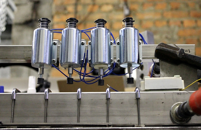
The first bowed instrument robot we designed was <Hurdy>,
an automated hurdy gurdy, built between 2004 and 2007. The building of that
robot had many problems and our attempts to solve these have lead to many new
ideas and experiments regarding acoustic sound production from bowed strings.
Between 2008 and 2010 we worked very hard on our <Aeio>
robot, where we used only two phase electromagnetic excitation of the twelve
strings. Although <Aeio> works pretty well, it can not serve as a realistic
replacement of the cello as we first envisaged it. The pretty slow build-up
of sound was the main problem. The cause being the problematic coupling of the
magnetic field to the string material. Thus we went on experimenting with bowing
mechanisms until we discovered that it is possible to excite the string mechanically
synchronous with the frequency to which it is tuned. For such an approach to
work well, we need a very precize synchronous motor with a very high speed.
Change of speed ought to be very fast, thus necessitating a low inertia motor
as well as a fast braking mechanism. Needless to say, but the motor should also
run as quietly as possible. To relax the high speed requirement a bit, we designed
a wheel mounted on the motor axis with ten plectrums around the circumference.
Thus for every single rotation of the spindle, the string will be plucked ten
times. Follows that in order to excite a string tuned to 880Hz, we need a rotational
frequency of 88Hz. Or, stated in rotations per minute: 5280 rpm. The motor type
ought to be a synchronous reluctance motor, since this type has no slip and
can be frequency controlled with high precision. Fortunately we could dig up
a suitable precision motor made by Eastern Air Devices. It's a spare part, custom
made for an American military airplane.
Since the tuning of the string is very critical, we did strive at making the
robot autotuning. Such a mechanism entails yet another motor specification problem.
The tension on the string obtainable from the motor ought to be at least 600N.
Such force values indicate the use of some kind of gears as well as a motor
with slow speed and very high starting torque. This brought another type of
motor we had on our shelves into sight: a General Electric synchronous inductor
motor. The principle connection diagram is:  Its torque (moment) is specified as 150 Oz.In., the anachronistic imperial equivalent
of 1.059 Nm in standard SI units. This motor is used to drive, via an intermediate
1:10 dented wheel construction, a worm gear -horizontal in the drawing- without
backlash,
Its torque (moment) is specified as 150 Oz.In., the anachronistic imperial equivalent
of 1.059 Nm in standard SI units. This motor is used to drive, via an intermediate
1:10 dented wheel construction, a worm gear -horizontal in the drawing- without
backlash,  the
large wheel being connected to the 12 mm take up spindle for the string. The
reduction ratio of the worm gear is 1:4. The maximum force, leaving out all
losses, we could have available to excert on the string now is 6.6 kN. We estimate
that the sum of losses suppers up more than half of this force. Designing an
autotune mechanism means that we also need to provide a sensor to measure the
string pitch accurately. For strings made of ferromagnetic material, an inductive
sensor or a coil wound on a permanent magnet can be used, but if we want to
use other types of strings, either optical sensing or a contact microphone is
needed. During the tuning procedure, the string has to be excited. Either the
motor-exciter has to run at its lowest possible speed, just plucking the string
at its free resonant frequency, or we can use the build-in feedback mechanism
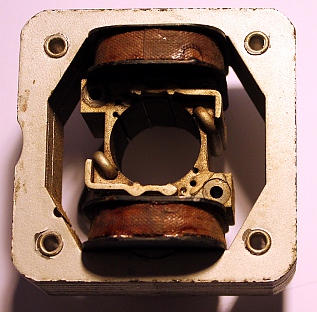
if ferromagnetic strings are used. As an electromagnetic string exciter, we
used a synchronous shorted cage motor from which we removed the rotor completely.
The string comes to run through the circular hole left open now. An extra bonus
of this autotune approach is that it now becomes possible to apply vibrato on
the string sound during normal operation. However, this makes it essential that
the processor steering the string exciter and the processor called in for the
autotuning mechanism talk to each other..
the
large wheel being connected to the 12 mm take up spindle for the string. The
reduction ratio of the worm gear is 1:4. The maximum force, leaving out all
losses, we could have available to excert on the string now is 6.6 kN. We estimate
that the sum of losses suppers up more than half of this force. Designing an
autotune mechanism means that we also need to provide a sensor to measure the
string pitch accurately. For strings made of ferromagnetic material, an inductive
sensor or a coil wound on a permanent magnet can be used, but if we want to
use other types of strings, either optical sensing or a contact microphone is
needed. During the tuning procedure, the string has to be excited. Either the
motor-exciter has to run at its lowest possible speed, just plucking the string
at its free resonant frequency, or we can use the build-in feedback mechanism
if ferromagnetic strings are used. As an electromagnetic string exciter, we
used a synchronous shorted cage motor from which we removed the rotor completely.
The string comes to run through the circular hole left open now. An extra bonus
of this autotune approach is that it now becomes possible to apply vibrato on
the string sound during normal operation. However, this makes it essential that
the processor steering the string exciter and the processor called in for the
autotuning mechanism talk to each other..
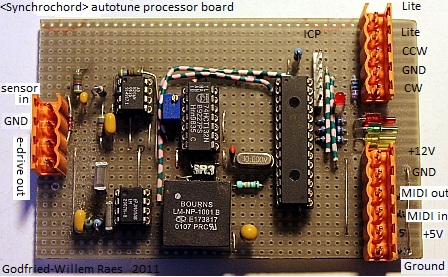
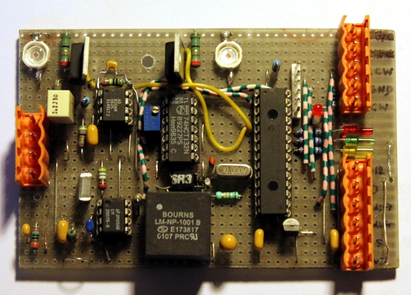
The circuit for the autotuner looks like:
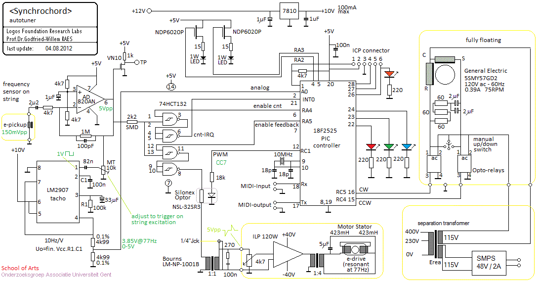
In the circuit the pick-up element is first amplified and then fed to a TTL
buffer with Schmitt-trigger inputs. The square wave that results is connected
to the hardware interrupt pin (INT0) on the PIC microprocessor, where a counter
is programmed in the interrupt handler to measure the exact frequency. The preamplified
signal from the pick-up is also presented to the input of the tacho (LM2907).
This component outputs an analogue voltage proportional to the frequency. This
analog voltage is presented the the A0 analog input of the PIC. Before sending
any commands to the motor, the PIC software always checks both the values on
the analog input with the values of the frequency counter. Only when these are
consistent, the motor will enter the control loop. We designed this redundancy
in as a safety measure, since breaking strings can be pretty harmfull, both
to the robot as well as to the people using it. It should be noted that in fact,
frequency measurement is more precize in the tacho approach then it is using
the counter. Since the gate time for the counter is 1 second, the count value
will inherently be plus or minus 1 count. For frequencies we are dealing with
here, this entails a precision worse than 2%. The tacho at the other hand is
sampled at 10 bits, a much better precision.
Once tuning is completed, the microcontroller will continue to monitor string
frequency and send out the data via its midi-out port. A midi controller (nr.80)
allows users to choose the messages send. Circuit elements drawn enclosed in
a yellow block, are mounted outside the printed circuit board.
The basic (and default) midi note mapping is:
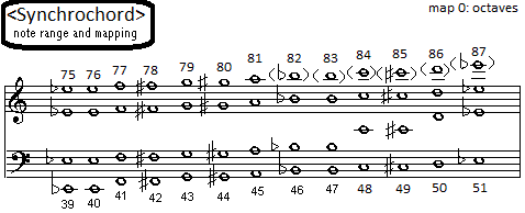
This is a mapping only using octave overtones. It minimizes
the inharmonicity of the string. An alternative mapping is: 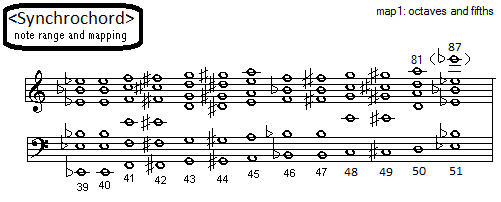
As one can tell from this, the lowest octave is again played
as fundamentals, whereas for higher notes string excitation makes use of overtones
2 to 5 or 6. The thirths are left out for they tend to be too much out of tune.
As can be read from the note range, we could also have implemented only 6 or
7 frets without loosing possible high notes, but we would have a gap in the
bass.
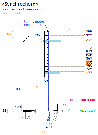
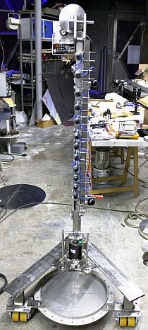
Since <SynchroChord> was designed to be a fretted instrument,
we had to design an automated neck and fingerboard. Starting from the theoretical
design rules 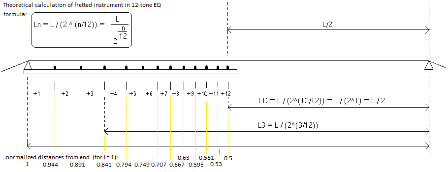 and taking into account that practical values for the fret sizes will have to
be somewhat smaller in order to account for the added string tension caused
by shortening the strings under pressure, we could calculate the minimum stringlength
required to meet technical considerations. If we plan to use Blacknight solenoids
as pushers for the frets, taking into account their smallest mounting size (42mm),
the total string length cannot be taken any shorter than 1400 mm. The frets
are designed to be adjustable, such that if one wishes to do so, other tunings
than standard EQ are possible. The 'fingering' solenoids are mounted on a square
stainless steel tube 25 x 25 x 3 mm with counterplates such that they can be
moved to an optimum match with the actual fretting. These solenoids use conical
return springs, essential since they have to operate in a horizontal plane.
For the fingers we used M4 rubber vibration dampers with an external M4 thread.
These type do not have the usual metal counterplate. Note that with this solenoid
assembly it became perfectly possible to implement finger vibrato, by modulating
the voltage to the solenoids after striking the frets.
and taking into account that practical values for the fret sizes will have to
be somewhat smaller in order to account for the added string tension caused
by shortening the strings under pressure, we could calculate the minimum stringlength
required to meet technical considerations. If we plan to use Blacknight solenoids
as pushers for the frets, taking into account their smallest mounting size (42mm),
the total string length cannot be taken any shorter than 1400 mm. The frets
are designed to be adjustable, such that if one wishes to do so, other tunings
than standard EQ are possible. The 'fingering' solenoids are mounted on a square
stainless steel tube 25 x 25 x 3 mm with counterplates such that they can be
moved to an optimum match with the actual fretting. These solenoids use conical
return springs, essential since they have to operate in a horizontal plane.
For the fingers we used M4 rubber vibration dampers with an external M4 thread.
These type do not have the usual metal counterplate. Note that with this solenoid
assembly it became perfectly possible to implement finger vibrato, by modulating
the voltage to the solenoids after striking the frets.
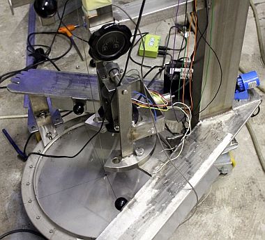
The string is attached to the center of a membrane resonator
made of 0.5mm thin stainless steel mounted on a 40cm diameter hub. The principle
is well known from asiatic instruments such as the gopi yantra or ektara. This
changes the acoustic properties of the string quite a bit from their usual behaviour.
Here the sense of the string vibration is under a straight angle to that of
the membrane vibration. After research performed and publisked by C.J.Adkins
(1981), this arrangement would cause the string to sound at twice its nominal
pitch. So the mechanism works as a frequency doubler in a way. Our experiments
show clearly that this does not fully hold, although it is true that the power
spectrum of the string contains a very strong octave component next to many
non-harmonic components.
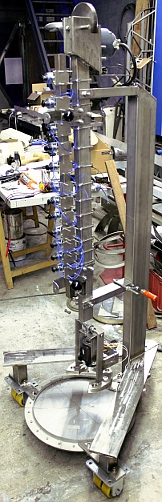
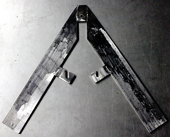
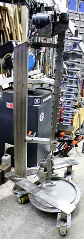
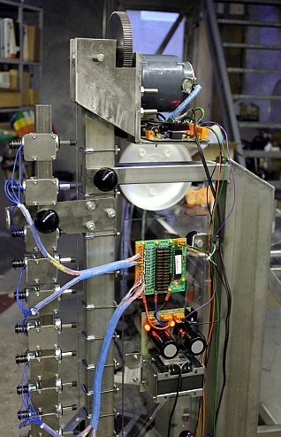
The constructional parts for this robot are all made from
welded stainless steel. The instrument is mounted on a wheel base, as most of
our music robots. In this case we went for a sturdy three wheel construction.
The wheels are in fact double wheels with yellow polyurethane tires. Only the
back-wheel can rotate in a horizontal plane.
The design of working circuitry for the string motor driver
(exciter) did cause a lot of headaches. The problems were related to malfunctioning
H-bridge drivers (IR2104 chips) on the one side, and than the problems caused
by the fast deceleration required from the motor spindle.
The circuit and the motor controller (an IB106) generates two
waves, 90 degrees out of phase, at a frequency 1/10th of the required pitch.
One input of the microcontroller is connected to a sensor measuring the actual
rotational speed. Any errors are regulated by the microcontroller. The motor
frequency signal is also output to the two 3W white LED's working as a strobe
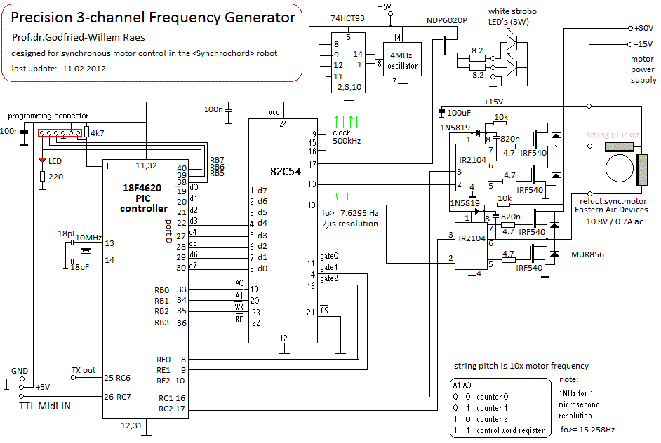
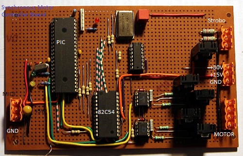
light on the spindle. The frequency generator makes use of 'old' technology:
the infamous intel counter chip, the 8254. This way the precision could be made
lot better than in the first versions using the mircrocontroller to generate
the phase shifted clock for the motor. A Microchip 18F4620 was used for the
microprocessor:
To improve response to changing speeds, we leave the motor
running for a while also after receiving a note off. The motor will come to
a complete standstill only after reception of a power down command. (Controller
66 with value 0). If it is envisaged to use <Synchrochord> in other tuning
systems, not only the frets have to be adjusted but also the frequency lookup
table in the firmware for this microcontroller.
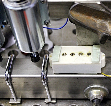
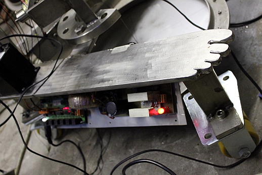
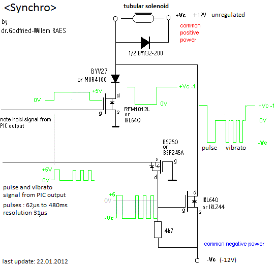
The damper, mechanically realized with a tubular solenoid,
is controlled by yet another PIC microcontroller, an 18F2525. The damper is
activated on reception of the note off command for the string. The noteoff-release
value controls the time the damper stays in contact with the string after a
note-off. This time interval is interrupted on reception of a new note on request
for the same string. The damping force can be controlled as well. By setting
controller 64 to %true, the damper mechanism can be disabled. On startup the
mechanism is always enabled. Note that none of the damper related controllers
(33,34,35,36) have an effect as long as sustain is on. The microcontroller however
will store any values send for these controllers such that they will be in effect
as soon as sustain (64) turns false. The power down command (controller 66)
resets all damper controllers to their default startup value.
Musically <Synchrochord> sounds quite a bit like a mediaeval
Tromba Marina. A bit harsh in sound at times. The historical trumpet marine
however, did not have any frets and its sounds were restricted to the high overtone
series of the single gut string. On our instrument, not that many overtones
can be produced due the the fixed position of the exciter with respect to the
sounding string length. The fingered vibrato on this instrument came out to
be very usefull. It certainly can be duplicated on just about any fretted instrument.
Also, as the attack force can be controlled 'left hand only' playing becomes
perfectly possible with very good dynamic control. On large interval jumps the
behaviour of the synchronous plectrum driver is a bit sluggish due to motor
inertia and thus the instrument is best suited for relatively slow moving string
bass parts.
Midi implementation and mapping: [under development, features in white
text are not yet implemented, features in purple
are only implemented for advanced users and for instrument development and research.
None of these controllers should be used in sequenced files ]
| |
|
- Midi note range: 39 - 81 (up to 87 implemented but shaky). Velocity
implemented: steers plucking depth.
- Note Off commands are required (dampers and motor brake) . Release
value implemented.
- Channel after touch: implemented (steers plucking
depth during a note)
- Controller 7: Volume controller for the ebow
mechanism (tuner board) Setting this controller to a non-zero value
automatically enables the ebow. This is implemented in the firmware,
but as we did find no space to mount the e-bow mechanism, it is as yet
without function..
- Controller 20: Set string tuning [defaults to
39] (tuner board)
- Controller 22: Autotune command (one shot, tuner
board) - do not use in a sequence!
- Controller 23: Enable e-bow mechanism (tuner
board)
- Controller 30: Release time control for finger
solenoids (pulse/hold board)
- Controller 31: Finger vibrato frequency (Pulse/hold board)
- Controller 32: Attack striking force for finger
solenoids, Duration of attack pulse. (Pulse/hold board)
- Controller 33: Attack duration for the damper solenoid (Hub-board)
- Controller 34: Release time control (hold time)
for damper solenoid (Hub-board)
- Controller 35: Attack force for the damper
- Controller 36: Holding force for the damper
- Controller 42: String Vibrato (tuner board).
This influences both depth and speed. The larger the depth, the slower
the speed will be. Value 0 switches this vibrato off.
- Controller 51: Adjust tuning [64= stop, <64=
lower pitch, > 64= higher pitch] (tuner board), Be carefull with
this controller as it is easy to break the string. Values are cumulative!
The parameter sets the time for the motor to run. Thus sending two times
CC51, value 96 is the same as sending CC51 with value 127 once. CC51
should never we used together with CC42 as their actions contradict
each other.
- Controller 60: Synchro motor PWM 1, motor force
(Synchro-motor board)
- Controller 61: Synchro motor current, motor
torque (Synchro-motor board)
- Controller 62: Synchro motor phase (Synchro-motor
board)
- Controller 63: Synchro motor - direction of
rotation (Synchro motor board)
- Controller 64, sustain (damper on or off, 0 = damper active) (Hub-board)
- Controller 65: Synchro motor time out value:
This determines how long the motor will continue to run after reception
of a note off command.
- Controller 66: power on/off switch (all boards)
. This controller also resets all controllers to their default startup
values.
- Controller 70: change the finger mapping lookup
table.
- Controller 80: controls the messages send through
the midi-out port according to the bits in the data word as follows:
- bit 0: if set, the measured frequency of
the string is output as a keypressure message (msb,lsb)
- bit 1: if set, the value of the tacho is
output as a pitchbend message (msb,lsb)
- bit 5: if set, a controller 51 with data
64 will be send on completion of the controller 51 command.
- bit 6: if set, a controller 22 with data
byte 127 will be sent to indicate the end of a tuning procedure.
- Controller 123: all notes off (also switches off the lights) (all
boards) . This command does not reset the controllers, so these retain
their programmed values.
- Program Change: not implemented yet.
- Pitch bend: implemented over a plus or minus
64 cents range. Only the 7-bit msb value is used. A pitch bend applied
to a note remains applied for repeated notes. On each new and different
note-on command, pitch bend will be reset automatically. Note that after
sending a new note-on command, at least a time of 1/4th of a wavelength
corresponding to 1 tenth of the frequency of the sounding note should
have passed for the pitch bend to be recognized. This is essential for
preservation of proper phase relations between the frequencies driving
the spindle motor. In the worst case, for midi note 39, this comes to
about 130 ms. (synchro motor board). The pitch bend command does
not change the tuning of the string.
- Lights:
- strobo-light (ON/OFF) (synchro motor board) - always follows note
on/off commands.
- mapped on notes 120-127, velo byte steers initial flashing frequency:
- note 120: (hub board)
- note 121: (hub board)
- note 122: Blue LED spotlite on arm left (hub board)
- note 123: Blue LED spotlite on arm right (hub board)
- note 124:
- note 125:
- note 126: 1W red LED on back side of tuning motor assembly (tuning
board)
- note 127: 1W red LED on front side of tuning motor assembly (tuning
board)
- Midi Channel: 10 (counting 0-15)
Synchrochord also has a midi output port, delivering information back
to the user, depending on the setting of controller 80:
- Key pressure: gives the sounding frequency of the string (in Hz),
format: status byte, msb, lsb (non standard use!)
- PitchBend, gives the 10bit reading of the tacho corresponding to the
string pitch. msb, lsb (non standard use!)
- Controller 22: value = 127 is returned when the autotune process has
finished.
- Controller 51: value = 64 is returned when a tuning command with CC51
was completed.
Synchrochord has two audio-output jack connectors, one carrying the signal
from the string pick-up and one offering the square waved version of this
signal. These signals are available for debugging purposes and for interactive
applications. They should not be used in normal orchestrations using the
robot orchestra, since such use would entail the use of amplification.
A video signal (composite video with a BNC connector) may be available
as well.
|
Technical specifications:
- sizes: height: 1700 mm, depth 650mm, width: 750 mm.
- weight: estimated ca. 45kg
- power: 235V / 100W
- tuning: autotuning on startup or on cold reset.
- strings: hardened spring steel, diameter 1.2 mm
- Ambitus: midi note 39 - 81 [87, if possible]
- Loudness level: to be determined. (tentatively 0 - 92 dBA)
- Insurance value: 13.000 Euro (first estimate)
Design and construction: dr.Godfried-Willem
Raes (2011-2012)
Collaborators on the construction of this robot:
- Johannes Taelman (firmware dsPIC controller)
- Xavier Verhelst (requisites and string research)
- Kristof Lauwers (application code)
- Sebastian Bradt (support)
- Laura Maes (support)
Music composed for <Synchrochord>:
- Godfried-Willem Raes
"Namuda Study #26", for <Korn>, <Synchrochord> and
a live viola player/dancer. (2012)
String selection table: [steel strings, sounding length 1400 mm]
| fundamental pitch |
diameter |
force |
comments |
| 39 (77Hz) |
0.7 mm |
140 N |
this is the smallest wire size used in piano's |
| id. |
0.8 mm |
183 N |
starting point for version 1.0 |
| id. |
0.9 mm |
232 N |
|
| id. |
1.0 mm |
287 N |
|
| id. |
1.1 mm |
347 N |
|
| id. |
1.2 mm |
413 N |
calculated ideal |
| id. |
1.3 mm |
485 N |
|
| id. |
1.4 mm |
563 N |
|
| id. |
1.42 mm |
|
bicycle brake stranded steel wire (gives gut-like sound) |
| id. |
1.5 mm |
646 N |
|
| id. |
1.6 mm |
735 N |
this is the thickest size ever used on piano's. 750 N is the
minimum force in piano's (1000 N max) |
Other strings and string materials tested:
- bass-guitar string, diameter 1.3mm (wound), tuned to midi note 39: sounds
too soft in volume. If tuned to 42 (F#) it breaks.
- Twisted multistranded steel cable as used for bicycle brakes: not very brilliant
sound, but flexible enough. Approaches gut-string sound. This was used during
the development of the robot.
Power supply calculation:
- - processors and logic: 5V DC - 3A max. (20 VA)
- - tuning motor: 120V / 0.4A - ac supply (48 VA)
- - finger solenoids, LED spotlites, softshift solenoid and damper solenoid::
+12V/ 10A, -24V/6A (150 VA peak)
- - exciter motor: +48V - 100VA (driven from separation transformer).
- - ebow amplifier: -40V - 0 - + 40V / 2.2A (120VA)
- - auxiliary voltages: +10V DC, + 12V DC (2VA)
Nederlands:
<Synchrochord>
Het eerste gestreken snaarinstrument dat we bouwden was de
hiervoor beschreven , een draailier gebouwd tussen 2003 en 2007. Het
resultaat van dat bouwprojekt was zeker niet onverdeeld gunstig: het ontwerp
lijdt onder vele bijgeluiden en gekletter. Ook de toonvorming met de boog verloopt
bijzonder onzeker. Niettemin konden we er veel lessen uit trekken en gaf het
ook aanleiding tot heel wat nieuwe experimenten. Het probleem van de aangestreken
snaren bleef ons bezighouden. Tussen 2008 en 2010 werkten we erg intensief aan
onze robot, alweer een poging om een oplossing te vinden voor het probleem
van de gestreken snaren. werd een aeolische cello waarbij we tweefazige
elektromagnetische excitatie van de twaalf snaren uitprobeerden. De resulaten
met waren -binnen de gestelde beperkingen- muzikaal helemaal niet zo
slecht, maar dat resultaat was nog wel mijlen ver verwijderd van een instrument
dat ook maar ergens in de buurt kon komen van een heus strijkinstrument. Een
goede robotische vervanger van de cello kon het heel zeker niet worden genoemd.
Het grootste probleem ervan was gelegen in de erg trage opbouw van de klank.
Die traagheid bleek een gevolg te zijn van de onderlinge koppeling van de magneetvelden
van beide tegenover elkaar geplaatste elektromagneten, waardoor de krachtoverbrenging
naar de snaar slechts minimaal bleek te zijn. De efficientie was bijzonder laag
en het stroomverbruik exorbitant hoog. Om dat te verbeteren zouden we eigenlijk
speciale elektromagneten moeten ontwerpen die in staat zouden moeten zijn een
uiterst gericht magneetveld op te wekken. Om de werking te versnellen zouden
we die bovendien moeten kunnen koelen tot cryogene temperaturen. Onhaalbaar
dus en zo gingen we door met onze experimenten. Zo belandden we bij het hier
beschreven bouwprojekt:
Hiervoor gingen we uit van een experiment waarbij we een snaar
in trilling brachten door ze mechanisch aan te slaan synchroon met de frequentie
waarop ze is gestemd. Voor zo'n aanpak is vereist een precizie synchroonmotor
te gebruiken geschikt voor een heel hoog toerental. Snelheidsveranderingen moeten
daarbij heel snel mogelijk zijn, wat dus een heel geringe inertie impliceert.
Ook een snel werkend remsysteem is noodzakelijk. Onnodig wellicht erop te wijzen,
dat die motor bovendien vrij moet zijn van eigen bijgeluiden. Om de vereiste
van dat hoge toerental toch enigszins binnen de perken te houden, ontwierpen
we een wieltje voor de motoras voorzien van tien plectrums (eigenlijk gewoon
dikke nylon draadjes) gemonteerd op de buitenzijde. Voor elke omwenteling van
de as, verkrijgen we zodoende tien aanslagen van de snaar. Hieruit valt eenvoudig
af te leiden dat om een snaar gestemd op 880Hz tot klinken te brengen, we een
toerental nodig hebben van 88Hz, of uitgedrukt in omwentelingen per minuut 5280
rpm. Dat is niet onrealistisch. Het motortype moet hiervoor een synchroon reluctance
motor zijn, met een heel geringe slip en heel nauwkeurig stuurbaar via de driefasige
ac frequentie. Gelukkig hadden we nog een geschikte precisie motor, gemaakt
door Eastern Air Devices, op voorraad. Een reserveonderdeel, speciaal gebouwd
voor gebruik in een bepaald type Amerikaans militair vliegtuig. Deze motor bouwden
we dus in, in onze experimentele robot.
Omdat de juiste stemming van de snaar bij een dergelijk opzet
erg kritisch is, streefden we ernaar de robot zelfstemmend te ontwerpen. Een
autotune mechanisme brengt evenwel alweer een heel ander probleem inzake motorselectie
met zich. De te ontwikkelen kracht voor de snaar die we wilden gebruiken moet
minstens 600 Newton zijn. Om een dergelijke kracht, binnen redelijke afmetingen,
te verkrijgen is de toepassing van een tandwielmechanisme aangewezen. De motor
moet een type zijn met een hoog aanloopkoppel en laag toerental. Hiervoor kwam
alweer een andere motor naar ons lonken: een General Electric synchroon inductiemotor.
Die moest op deze wijze aangesloten worden:
Het koppel vermeld op het schildje is 150 Oz.In., het anachronistisch
imperiaal equivalent van 1.059 Nm in standaard SI eenheden. We gebruikten deze
motor, via een 1:10 tandwieloverbrenging om een wormwiel aan te drijven vrij
van terugslag. Het grote wiel is daarbij vastgemaakt op de 12 mm haspel waarop
de snaar voor het stemmen is bevestigd. Rekening houdend met de reduktie verhouding
van het wormwiel en afgezien van alle wrijvingsverliezen, zou de maximale te
leveren kracht beschikbaar voor het spannen van de snaar nu 6.6 kN moeten belopen.
Naar onze inschatting, wordt evenwel zowat de helft van die kracht opgesoupeerd
in allerlei mechanische verliezen. Er blijft wel nog genoeg over... Een autotune
mechanisme vereist uiteraard ook een sensor waarmee de precieze toonhoogte van
de snaar gemeten kan worden. Aangezien we hier een ferromagnetische snaar wilden
gebruiken, blijkt een inductieve sensor bestaande uit een spoel gewikkeld rond
een permanente magneet heel geschikt. Voor andere snaarmaterialen zouden we
natuurlijk ook een optische sensor of een contactmicrofoon kunnen gebruiken.
Tijdens de stemprocedure moet de snaar natuurlijk ook tot trillen gebracht worden.
Daartoe kunnen we hetzij de exitatiemotor, draaiend op een heel laag toerental,
zodat we van de snaar alleen de eigenresonantie te horen krijgen gebruiken,
hetzij -bij gebruik van een ferromagnetische snaar, het ingebouwde feedback
mechanisme. Daarvoor gebruikten we een omgebouwde motor met kortsluitanker,
waarvan we de rotor volledig verwijderden. De snaar voeren we doorheen het ronde
gat dat nu open blijft. Als bonus van dit mechanisme, onstond nu ook de mogelijkheid
vibrato op de snaar toe te passen. Op voorwaarde natuurlijk, dat de processor
die instaat voor de besturing van de excitatiemotor en de processor belast met
het autotune mechanisme, met elkaar kunnen communiceren. De schakeling voor
de autotuner kwam er zo uit te zien:
In deze schakeling wordt het pick-up element eerst versterkt
en dan naar een TTL buffer gevoerd met Schmitt-trigger ingang. Zo wordt het
signaal omgevormt tot een propere blokgolf die we aansluiten op de externe interrupt
ingang (INT0) van de PIC microcontroller. Daarop programmeren we een teller
waarmee we de snaarfrequentie heel precies kunnen meten. Het voorversterkte
signaal bieden we eveneens aan op de ingang van een tacho chip, een LM2907.
Deze component zet het ingangssignaal om in een met de frequentie proportioneel
gelijkspanningssignaal dat we dan weer aanbieden op de A0 analoge ingang van
de microcontroller. Alvorens weldanige instruktie ook naar de motor te sturen,
kan de controller nu beide signalen op consistentie checken. Slechts wanneer
dit blijkt te kloppen, zal de firmware de stemmingslus in gang zetten. Dit bleek
een absoluut noodzakelijke beveiliging te zijn, waarmee vermeden wordt dat de
snaar tot voorbij de breukgrens wordt opgewikkeld. Dat is immers gevaarlijk,
niet alleen voor de robot zelf, maar ook voor menselijke omstaanders en gebruikers.
Opgemerkt moet worden dat -enigszins ingaand tegen onze intuitie- de frekwentiemeting
van de tacho nauwkeuriger is dan die van de frequentieteller. De meettijd van
de teller is immers 1 sekonde en dus is de precisie beperkt tot plus of minus
1 eenheid. Voor de frequenties waarmee we hier te maken krijgen leid dit tot
een nauwkeurigheid in de orde van 2%. De tacho anderzijds, heeft een resolutie
van 10 bits, wat een betere resolutie oplevert. Vanzodra het stemproces is afgelopen
-het verloopt opzettelijk vrij traag- gaat de microcontroller door met het meten
van de toonhoogte van de snaar en zal hij het resultaat van de doorlopende meting
als een datastroom op zijn MIDI-uitgang plaatsen. Midi controller 80 laat gebruikers
toe het dataprotocol in te stellen.
De default midi-mapping ziet er zo uit: In deze mapping gebruiken
we alleen oktaaf boventonen van de snaar. Hierdoor minimaliseren we de inharmoniciteit.
Een alternatieve mapping, met meerdere boventonen is echter
ook mogelijk:
Zoals we kunnen zien, gebruiken we hier voor het laagste oktaaf
alleen de grondtonen, terwijl we voor de hogere noten de snaar exciteren met
de boventonen 2 tot 5 of 6. De tertsen lieten we achterwege omdat die teveel
van de gelijkzwevende stemming afwijken. We hadden natuurlijk kunnen volstaan
met slechts 6 of 7 fretten zonder verlies aan spelmogelijkheden in de hoogte,
maar dan zouden we wel een gaatje krijgen in de laagste regio van de tessituur.
was van meet af aan ontworpen als instrument met fretten. Dus
dienden we ook een soort hals en een toets te voorzien. De positie van de fretten
konden we op deze wijze berekenen:
De praktische afstanden voor de plaatsing van de fretten moesten
we iets kleiner nemen dan berekend,omwille van de gewijzigde snaarlengte en
spanning wanneer de snaar wordt ingedrukt. Wanneer we sterkte Blacknight solenoiden
als 'vingers' voor het indrukken van de snaar willen gebruiken dan komen we
-rekening houdend met de kleinst mogelijke montageafstand (42mm)- uit op een
minimale snaarlengte van 1400 mm. We maakten de fretten zo, dat de plaatsing
instelbaar is. Naar wens van de gebruikers, kunnen dus ook andere stemmingen
en temperamenten gebruikt worden. De 'toets' waarop we de duwmagneten voor de
'vingers' verplaatsbaar monteerden bouwden we op een lengte roestvast staal
profiel 25 x 25 x 3 mm. De duwnagneten zijn uitgerust met conische veren, nodig
voor het terugkeren van de ankers aangezien we hier horizontaal werken. De 'vingers'
zelf vervaardigden we met trillingsdempers voorzien van een M4 schroefdraad.
Deze konstruktie maakt vibrato door modulatie van de drukkracht mogelijk.
De snaar is onderaan vastgemaakt op het middelpunt van een
0.5mm dik roestvast stalen membraan dat als resonator fungeert. Het membraan
zelf is vastgeklemd in een hoepel met een diameter van 400 mm. Dit type resonator
is ons wel bekend uit verschillende asiatische instrumenten zoals de gopi yantra
of ektara. Zo'n resonator wijzigt evenwel de akoestische eigenschappen van de
snaar in aanzienlijke mate. De snaar komt immers loodrecht op de resonator te
staan en niet evenwijdig ermee zoals bij gebruikelijke snaarinstrumenten. C.J.Adkins
(1981), onderzocht de gopi yantra vanuit akoestisch perspektief en toonde aan
dat een dergelijke constructie de snaar doet octaveren naar omhoog. Het werkt
dus als een frequentieverdubbelaar. Onze eigen experimenten en metingen wezen
uit dat die bewering toch niet helemaal klopt, alhoewel we kunnen bevestigen
dat de spectraalanalyse van het door de snaar voortgebrachte geluid, inderdaad
een heel sterke octaafcomponent bevat, evenals trouwens, een heel groot aantal
volstrekt niet-harmonische spectraalcomponenten.
De hele robot werd gebouwd met roestvast staal en gemonteerd
op een stevig wielstel met gele massieve polyurethaanbanden. De ontwikkeling
van een goed werkende schakeling voor de besturing van de tokkelmotor heeft
ons vele hoofdbrekens bezorgd. Problemen met slecht werkende driverchips voor
de H-bruggen (IR2104 chips) enerzijds en problemen als gevolg van het noodzakelijke
snelle versnellen en vertragen van de motoras anderzijds, lagen aan de basis.
We zagen heel wat opgebouwde schakelingen letterlijk in rook opgaan. Uiteindelijk
gebruikten we een IB106 motor controller, waarmee we de nodige twee sinus spanningen,
onderling 90 graden in fase verschoven, met een frequentie gelijk aan een tiende
van de gewenste toonhoogte konden opwekken. De microcontroller voor de besturing
gebruikt een van zijn ingangen voor het meten van de rotatiesnelheid met een
sensor. De motorspanning gebruikten we bovendien om ook twee 3 W sterke witte
LED's te doen werken als stroboscoop licht gericht op het plectrumwiel. De frequentie
generator die we ontwierpen voor de motorsturing, maakt gebruik van 'oude' technologie:
de vroegen alomaanwezige Intel tellerchip 8254. Met deze chip konden we een
nauwkeurigheid bereiken die heel wat beter was dan wat we konden bereiken met
een 8 bit microcontroller voor het genereren van de fase-verschoven signalen.
Hier is het volledige ontwerp: Om de responssnelheid bij veranderende motorsnelheden
wat te verbeteren, lieten we de motor ook na ontvangst van een noot-uit instruktie,
doorlopen. Alleen wanneer een uitschakelcommando wordt gegeven, valt de motor
helemaal stil. De demper, opgebouwd met een vilten strip aangedreven door een
rond elektromagneet wordt door een eigen 18F2525 microprocessor bestuurd. Hij
wordt aktief bij ontvangst van een noot-uit commando. Een heleboel parameters
laten toe de demper op een erg genuanceerde wijze te besturen. Daarvoor gebruikten
we de midi controllers 33,34,35 en 36.
Muzikaal gezien klinkt ons een beetje zoals
een middeleeuwse tromba marina. Een beetje ruw van toon. De historische tromba
marina evenwel, is een eensnarig instrument zonder fretten. De tonen die het
kon voortbrengen waren beperkt tot de hogere boventonen van de darmsnaar. Op
ons instrument zijn niet zoveel boventonen speelbaar omdat de plaats van de
plectrum/strijker vast ligt. Het vingervibrato bleek bevredigend te werken en
kan zeker als een model gebruikt worden voor later nog te ontwikkelen instrumenten.
Omdat de aanslagkracht van de vingers heel goed bestuurd kan worden, is spelen
'met de linkerhand alleen' heel goed mogelijk. Het gedrag van plectrumwiel daareentegen
laat veel te wensen: het is eigenlijk veel te traag in zijn reaktie op toonhoogtewisselingen.
Voor traag bewegende contrabaspartijen is af en toe wel bruikbaar.
We hebben ook voor <Synchrochord> een beknopt bouwdagboek
in het engels bijgehouden. Omdat we de bouw tot in de laatste details graag
illustreren, kan het ook voor anderen die ons op dit pad willen volgen en/of
verbeteren, van praktisch nut zijn.
Construction & Research Diary:
- 06.08.2011: first sketches and designs on paper. Research on useable motor
technologies. At first Maxxon motors came to our mind, but with only 10-bit
precision on speed, even their best types wouldn't match our criteria.
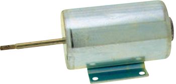
- 07.08.2011: Calculation of sizing. Principle design of the setup. Start
of this webpage. Eastern Air Devices motor digged up in the lab. Its a very
high quality motor, though in principle too heavy.
The mounting plate seems ideal to let the string pass and it even has a slot
for an optical speed sensor. Start welding works on a suspended mount for
this motor. The rotation axis was selected as 12 mm. All parts to be constructed
from stainless steel.
- 08.08.2011: Design of the cardan shaft to be used for pushing the rotator
against and away from the string. This cardan shaft connects the Lucas Ledex
softshift solenoid to the suspended motor cradle.
 After building this up, it came out not only that it didn't work, but moreover
that this design is plain impossible. Cardan shafts cannot be used to solve
the linear to circular motion problem... Systems using a sliding component
were also rejected because of the hystereris and the noise they introduce.
Finaly we found a pretty easy solution: we made a M6 threaded hole in the
motor mounting plate (aluminium) and mounted a hexagonal inbus setscrew in.
Next we simply connected the anchor of the softshift solenoid (1/4" side)
to the free end of the setscrew using a small length of flexible rubber tubing.
This works and has the advantage of ease of adjustment and silent operation.
The rubber tubing will need replacement every so often though. Note that the
softshift solenoids come with an UNF thread!
After building this up, it came out not only that it didn't work, but moreover
that this design is plain impossible. Cardan shafts cannot be used to solve
the linear to circular motion problem... Systems using a sliding component
were also rejected because of the hystereris and the noise they introduce.
Finaly we found a pretty easy solution: we made a M6 threaded hole in the
motor mounting plate (aluminium) and mounted a hexagonal inbus setscrew in.
Next we simply connected the anchor of the softshift solenoid (1/4" side)
to the free end of the setscrew using a small length of flexible rubber tubing.
This works and has the advantage of ease of adjustment and silent operation.
The rubber tubing will need replacement every so often though. Note that the
softshift solenoids come with an UNF thread!
 Fortunately
we could dig up some suitable nuts in our workshop. The pictures show the
exciter module, as yet without mounting base nor provision for a damping mechanism.
If we would change the design such that the suspended part could move left-right
in its axis of rotation, the mechanism would be perfectly suitable as an exciter
in a multi-stringed instrument.
Fortunately
we could dig up some suitable nuts in our workshop. The pictures show the
exciter module, as yet without mounting base nor provision for a damping mechanism.
If we would change the design such that the suspended part could move left-right
in its axis of rotation, the mechanism would be perfectly suitable as an exciter
in a multi-stringed instrument.
- 09.08.2011: Honing and grinding works for precision allignment of the cradle
mechanism. Welding of the structural unit to a bottom plate, a flange with
a cut-out to let the string pass through easily.
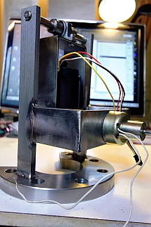 Now we can go on with the design of the drive electronics for this unit before
we go on with the design of the entire projected robot.
Now we can go on with the design of the drive electronics for this unit before
we go on with the design of the entire projected robot.
- 10.08.2011: Study of the design for the speed sensor. Pepperl+Fuchs NEMA
proximity sensor seems suitable. Type NJ2-V3-N (NAMUR-type): we can operate
this from the 5V supply and they have a reasonably large analogue traject
(ca. 6 mm), as figured out with <Korn>.
- 11.08.2011: Mounting of the 8 stud bolts (M3 x 12) pointing to the inductive
sensor. Thus the sensor will output 8 pulses per revolution. Since we will
have 10 plectrums on the exciterwheel. For the development of the firmware
we will have to keep in mind following intrinsic relationships:
- frequency of the sounding pitch = 5/4 frequency of the sensor
- frequency for the motor = frequency of the sounding pitch / 10
- frequency for the motor = frequency of the sensor / 8
- First tentative construction of plectrums for the exciter. These are made
from a rod of M4 threaded nylon.
- 12.08.2011: To facilitate allignment and measurement of slip, we designed
a strobo-light on the excitation spindle. If we strobe the light at the frequency
of the motor, we should see the effects of slip. Two 3W white LED's are used
here. Type: Lumiled, Luxeon 5109LXHLMWEC, SV0H 8013962.
- 13.08.2011: String calculations within the constraints of the design. Digging
up our old software for calculation of string parameters. Looks like sounding
string length will have to become 1400 mm, with a thickness of ca. 1.2mm,
using pianowire.
- 14.08.2011: Damn! The push type solenoids from Black Knight we planned to
use (type 124 420 620 620) went out of production. We used them before in
robots such as <Simba>, <Bako>, <Bono> and <Snar>...
Looks like a redesign will be required. Back to Lucas-Ledex?
- 15.08.2011: Start construction of a possible resonator: 0.5mm thick stainless
steel on a rim with outer diameter 480mm. The string should connect to the
center of the circle. Design of the tuning mechanism.
- 16.08.2011: Start construction of the auto-tuning mechanism. Finding suitable
gear wheels is not an easy matter it seems... Alternative tubular solenoids
traced at Conrad: ZMF 38640.002 or ZMF-3258D.002..
 These are made by Tremba Gmbh. in Germany. The sizes have a striking similarity
with the Black Knight types, though they are a lot cheaper.
These are made by Tremba Gmbh. in Germany. The sizes have a striking similarity
with the Black Knight types, though they are a lot cheaper.
- 18.08.2011: Dented wheels in steel, module 1, ordered from Gallon bvba.
Less expensive than we thought.
- 19.08.2011: Delivery of the finger solenoids by Tremba. They use conical
return springs and have 60 degree plungers. The counter plates for a moveable
mount on a stainless steel square tube 25x25x3 have to be 42x38. Mounting
with M3 x 30 or M3.5 x 30 bolts and nuts. Research on the possibility of implementing
finger vibrato by slow PWM'ing the fret solenoids, taking into account that
the pushing force they excert is a function of applied voltage. Of course
this entails provisions for pretty high elevated frets (sort of like on the
dilruba or the sitar).
- 20.08.2011: Design of the fingering chassis.
- 22.09.2011: Only now the dented wheels for the tuning mechanism came flowing
in from Gallon bvba... Now we can go on with the works.
- 25.09.2011: Cutting out of the slots for the dented wheels in the tuning
head. Further design of the mechanical construction and the motor suspension.
- 09.10.2011: Filing of the slots for the tuning motor adjustment. This takes
forever in 10mm thick stainless steel, wish I had a mill to do this.
- 03.11.2011: TIG welding of distance holder in tuning head. Preliminary assembly
of the tuning head with motor, gears and string spindle.
- 04.11.2011: Adjustment of the sliding slots for the dented wheels.
- 05.11.2011: Further design of the tuning motor control circuitry. Construction
of the large wheel pickup axle: two sunken M4 bolts hold a small steel plate
through M4 threads made in the dented wheel. A 4 mm splitpen -if this would
prove not to be strong enough, we can replace it with a 4mm hardened steel
pin- connects this block horizontally through the hole in the spindle of the
wormwheel. Mounting plate welded on for the R-C network. The 175 Ohm/ 50 W
resistor was realised using three 60 Ohm wirewound power resistors connected
in series. The 4uF capacitor is made using two 2uF AC caps (Siemens) we found
on our shelves.
- 06.11.2011: Test of the tuning motor and the mechanism. Start work on the
fretboard. Cut from 50x30x2 stainless steel profile. The solenoids will be
mounted on a rail made from 25x25x2 profile. Construction of the mounting
plates for the solenoids. Material thickness: 2 mm. Each plate has 4 holes,
3 mm diameter. Mounting will be with M3 x 35 hex inbus bolts.
- 07.11.2011: M3x35 inbus bolts ordered from MEA. Rubber finger pushers ordered
from Farnell: Fivistop 1008VE10-45. These have M4 threads and can take a maximum
load of 9.5kg with 2mm compression. Order code: 499-7220.
- 08.11.2011: Construction of the 12 holding plates for the frets. 15 mm wide,
40 mm long , 2 mm thick with two 3 mm holes at a distance of 35 mm.
- 09.11.2011: Ordered parts from Farnell flown in. The frets use part nr.3058517
but 0.5 mm of material had to be filed off from the insides such that the
distance between the stand-off's becomes 30.0 mm. We can mount these using
two M3 x 50 bolts.
- 10.11.2011: Test mount of the fingering solenoids over the 25 mm square
bar.
- 12-13.11.2011: Further design of the circuitry for the autotuning mechanism.
Experiments conducted with regard to the usefullness of synchronous motor
stators as string exciters. Two squirrel-cage motors were dismantled by removing
the squirrel-cage anchor. The round whole is now used to let the ferromagnetic
string pass through. Note that these motors are torque motors, that can be
stalled at all times. For startup under normal operation, they have two shadow
poles realized with thick rods or bars of copper that form a closed electric
circuit. These poles generate a slightly delayed magnetic field large enough
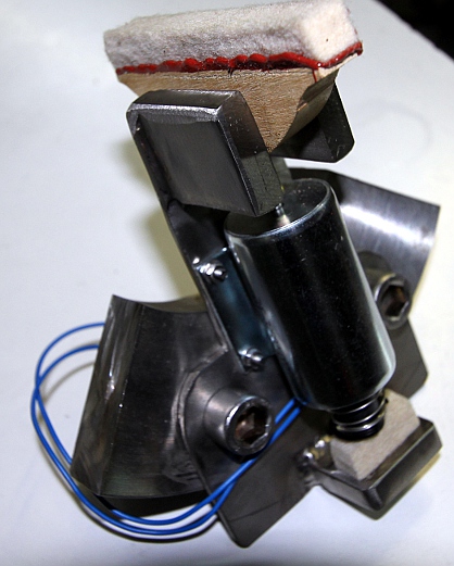
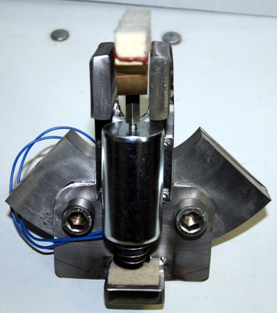
for the motor to start. The first motor after dismantling looks like:
 This motor was probably designed to operate on 120V ac with the two windings
in series, so with the two windings in parallel, 60V should be workable. The
inductance is 200mH (in parallel) or 800mH (in series). The second motor,
designed to run off 230V is of a much simpler construction:
This motor was probably designed to operate on 120V ac with the two windings
in series, so with the two windings in parallel, 60V should be workable. The
inductance is 200mH (in parallel) or 800mH (in series). The second motor,
designed to run off 230V is of a much simpler construction: 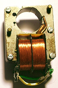 Its inductivity is a lot higher. It can be used on 120V with both windings
in parallel. Our experiments revealed that in fact these motor stators can
make good string drivers, but the string ought to be fed through the hole
slightly off-center. The exact center has a zero magnetic field.
Its inductivity is a lot higher. It can be used on 120V with both windings
in parallel. Our experiments revealed that in fact these motor stators can
make good string drivers, but the string ought to be fed through the hole
slightly off-center. The exact center has a zero magnetic field.
- 14.11.2011: Completing the calculations for the tuning electronics. Electronic
hardware design. First draft for the firmware for the tuning microcontroller.
The source code development can
be followed here.
- 15.11.2011: Further measurements with the torque-motor stators under varying
frequency conditions.
- 16.11.2011: Since it seems quite impossible to get suitable P-channel IGBT's,
we changed our design such as to use a pure analogue drive for the exciter
coil.
- 17.11.2011: Start soldering work on a breadboard for the autotune electronics.
- 18.11.2011: Measurement and selection of suitable pick-ups. Sofar, a bass
guitar pick-up seems to work out best.
 It should find a place pretty close the the highest fret, since we are only
interested in the fundamental frequency, not in the sonic properties of typical
string sound. The placement of the pick-up lengthwize also helps to emphasize
the lowest frequencies.
It should find a place pretty close the the highest fret, since we are only
interested in the fundamental frequency, not in the sonic properties of typical
string sound. The placement of the pick-up lengthwize also helps to emphasize
the lowest frequencies.
- 19.11.2011: Continuing work on the breadboard for the autotuner. Selection
of a suitable 1:1 transformer. Bourns LM-NP-1001B seems suitable.
- 20.11.2011: Measurements and first tests on breadboard.
 External connections shown in the picture.
- 23.11.2011: Further tests on breadboard. The PIC firmware is running, though
we cannot check whether or not its doing the things it is supposed to do.
The tacho circuit measures out o.k., but the frequency ripple is with 350mVpp
way too large. Response it pretty fast.
- 24.11.2011: Tacho circuit recalculated: with C2 = 33uF we can achieve ripple
values below the 10 bit ADC resolution (9.7mV), but this increases the settle
time to ca. 3.3 s. With the component values now, we have 8.6mVpp ripple.
- 27.11.2011: Fine milling and adjustment of the tuning head such that there
is no longer any play between the gear wheels. 10V voltage regulator added
to tuning motor PC board for tacho powering. We used a small 78L10 regulator,
since we draw only a few mA's.
- 28.11.2011: Welding, milling and cutting works on the upper bridge. Test
assembly of tuning head and neck together. Threaded spacers, 20mm long, with
female M4 threads ordered from Farnell: order number: 957-136, as well as
half bridge driver IC's for the synchronous motor driver.
- 29.11.2011: Start works on the wheelbase and the vertical column.
- 06.12.2011: Sawing and milling of the mounts for the frontal double wheels.
Sawing and TIG welding of the vertical column on the backwheel support wheel.
 Principle sizings
determined and drawn out.
Principle sizings
determined and drawn out.
- 07.12.2011: Designs for fingerboard holder. Should be adjustable over a
small range.
- 10.12.2011: Square posts, 50x50x120 stainless steel cut for welding on the
front wheels. These determine the exact place for the string exciter motor.
- 12.12.2011: Square posts welded on the wheel bases.
- 13.12.2011: Cutting out of the frontal 'legs' from 10 mm thick stainless
steel. Redrawing the welding plan. This is the base chassis, welded together:
- 14.12.2011: Inventary of power supply requirements and planning for mounting
space for them.
- 18.12.2011: Further design and construction work: mounting slide for the
plucking assembly.
- 19.12.2011: Continuing work on the mounting slide for the plucker. We are
giving a few millimeters of game to the sledge to allow for minor adjustments.
The motor assembly will be mounted on the sledge with two M14 bolts. The holes
in the flange are 20mm in diameter.
- 24.12.2011: Construction of the power supply for the plucking motor. Here
we could make use of an old and proven design developed for our invisible
instrument back in 1993. We still had a spare PC board, made in 1995 ready.
The circuit is:
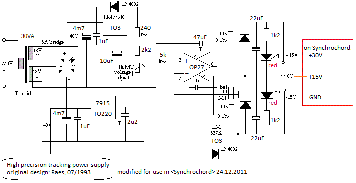 It
all fits nicely on a Eurocard 100x160 mm. The precision achieved in this design
is not required at all for this application, but the adjustability of the
output voltage comes in handy. Taking into account the current required for
the motor, a 30VA rated transformer should do the job.
It
all fits nicely on a Eurocard 100x160 mm. The precision achieved in this design
is not required at all for this application, but the adjustability of the
output voltage comes in handy. Taking into account the current required for
the motor, a 30VA rated transformer should do the job.
- 25.12.2011: The DC cold resistance of the Trembla solenoids is 11 Ohms.
If we anticipate that there will be at the very most 5 solenoids active at
the same time, a +12 V power supply of ca. 65 Watt should do the job. If we
take -12V with the same rating for the pulse supply, a 150Watt power supply
reaches out.
- 26.12.2011: Further work on the printed circuit holding chassis parts.
- 27.12.2011: Slot for the electromagnetic pick-up sawn out on the fingerboard.
Vertical standoffs for the solenoid bar mounting on the fingerboard constructed.
These are removable and held in place with 2 times 3 M8 x 45 bolts. Mounting
gallows for the solenoids and fingerboard assembly on the vertical column
welded on. Tuning motor block welded on the vertical column.
- 28.12.2011: First tentative assembly of all essential chassis components.
Welding of the vertical pole on the base chassis.
 The transformer for the tuning mechanism mounts on the base plate with M5
bolts. We threaded holes in the bottom plate.
The transformer for the tuning mechanism mounts on the base plate with M5
bolts. We threaded holes in the bottom plate.
- 29.12.2011: Workshop cleanup and inventory of missing parts for the synchrochord.
We decided to give it toes, modelled after mine.
 Drawing of different versions for the e-bow holder. This has to be adjustable
over a pretty wide range, both vertical and horizontal.
Drawing of different versions for the e-bow holder. This has to be adjustable
over a pretty wide range, both vertical and horizontal.
- 30.12.2011: Further workshop cleanup and construction of the side panels
holding the electronics. Left side: +/- 15V supply, 5V transformer, midihub
board. The right side may get the 12V supply and the audio amplifier for the
electromagnetic exciter. Consultation with Johannes Taelman on the synchronous
motor drive processor.
- 31.12.2011: Welding works on the holding structure for the electromagnetic
drive stator.
- 06.01.2012: Drilling and milling of hole in the tuning pin. Construction
of a string end flange. First test with a wound and polished bass guitar string,
1.3 mm thick. This gives a way too low sound volume, but it's good enough
for performing fine adjustment of fret-heights and neck tilt.
- 09.01.2012: Further filing and adjusting of frets.
- 12.01.2012: Some more fret-works...
- 14.01.2012: All frets are alligned now. We also finished the adjustments
for the solenoid pushers. Mounting of the PIC controller board for these can
take off now.
- 15.01.2012: Welding of holding plates for the support plate for the pulse/hold
board on the large vertical column.. Sawing of the board from 8 mm thick polycarbonate
(540 mm x 160 mm). Start wiring of the solenoids to the 16-pole Weidmueller
connector on the board.
- 16.01.2012: Simple power supply made for the solenoids. Stabilising is not
required here. For the first tests we may go with a _12V / - 12V, 2 x 3.3
A supply instead of the +12V / - 24V we would use in real velocity sensitivity
applications. A power of 100 VA seems sufficient if we do not activate many
solenoids at once.
 This power supply reaches out for the simultaneous activation of 3 solenoids.
If we use one for the damper, we can still maintain an overlap of 2 active
pushing solenoids. First version for the PIC firmware for the finger-solenoids
programmed. The source code can be found here: SYNFingers.bas
This power supply reaches out for the simultaneous activation of 3 solenoids.
If we use one for the damper, we can still maintain an overlap of 2 active
pushing solenoids. First version for the PIC firmware for the finger-solenoids
programmed. The source code can be found here: SYNFingers.bas
- 17.01.2012: First version of the firmware for the midi-hub board written.
Source code: SynHub.bas. Start
development of test and torture code in GMT. Midi implementation table adapted
accordingly.
- 18.01.2012: Construction of mounting brackets for the bipolar power supply.
Mounting on the polycarbonate plate.
- 19-20.01.2012: Version 1.0 of the firmware for the solenoid finger control
ready and debugged on the test platform.
- 21.01.2012: Mounting brackets for the electronics holding chassis parts
welded on. The electronics chassis is mounted on the robot with two hex-inbus
M8 x 20 bolts. Wiring of the left side components: 0-15-30V power supply,
Logic power transformer, toroidal transformer. Firmware for Hub board loaded
in PIC. Looking for a solution for the mains power switch. Linear LT1084-12
regulator added on solenoids power supply board to make the operation of the
softshift solenoids independent on voltage fluctuations caused by the finger
solenoids. The LT1084-12 was choosen for it has a maximum current of no less
then 5 A.
- 22.01.2012: Mounting of the solenoid power supply on the polycarbonate carrier
plate. Wiring up of the installed power supplies as well as the 5V power and
midi connectors. First test-run on the actual robot with the firmware. Measurements:
the positive voltage (non-stabilized) sinks from 16.6V to 14.2V with one coil
switched on (hold). The negative voltage goes down to 14.6V. This is as expected.
The regulated 12V stays rocksolid under all conditions. For this version (V1.0)
of the fingering firmware, the most suitable (midi)value for the vibrato control
is between 4 and 8. So we may have to rescale this. Switching velo as well
as hold on together doesn't cause any harm to the electronics hardware, the
pulse mosfet's get a little more hot then in automates where we did not implement
hold and pulse together. No real need for cooling though under normal operating
conditions. Solenoids can get very hot, with the pulse on (or vibrato at a
high repetition rate) for a long time. Notice the slight modifications in
the control signals:
 After our observations, it seems appropriate to provide different pulse durations
for every single solenoid. The solenoid for the first semitone needs the highest
force.
After our observations, it seems appropriate to provide different pulse durations
for every single solenoid. The solenoid for the first semitone needs the highest
force.
- 23.01.2012: Mounting of the e-guitar pickup in the neck using coaxial cable.
Mounting of the first couple of lights: blue LED spotlites on two arms. Mapping
on notes 120 and 121, controlled by the hub-board.
- 24.01.2012: Two 1W red LED's added on tuning board. Mapping on notes 126
and 127. We operate them with a 15 Ohms series resistor with a current of
186mA, thus the delivered power is limited to 410mW for each LED. P-channel
mosfets are used for the switching. GMT test code expanded with light tests.
This works o.k. Schematic drawings updated. Midi-hub board tested with the
plucker softshift solenoid. This works o.k. at first sight. With the firmware
we are now at version 1.1 for both the midi-hub board and the tuner-board.
 Some workshop pictures made and added to this page.
- 25-26.01.2012: Further work on the coding for the autotuner board.
- 27.01.2012: Signal conditioning input section on tuner board improved. AD820
opamp circuit. The bass-guitar element gives a signal of 150mVpp. Background
noise and hum do not exceed 40mVpp. So we have to calculate the circuit such
as not to trigger on the (very high) noise. The gain of the input amp -with
the pickup connected- should therefore not exceed 33. Note that the impedance
of the pick-up should be taken into account when calculating amplifier gain.
- 28.01.2012: Increasing string tension, as can be expected, greatly improves
the sound quality but also creates problems with the fingering coil on the
first fret. The required force here can exceed what is possible with the solenoid.
Clamping diode on analog A0 PIC input in tuning board removed and replaced
with a stiff precision voltage divider. (2x 4k99, 0.1%). This way we can no
longer overload the PIC input. The calculated tacho voltage at a string frequency
of 78Hz is now 3.9V corresponding to a 10-bit reading of 798. PIC firmware
adapted accordingly. 1M feedback resistor over the input signal opamp paraleled
with a 100pF capacitor for better noise behaviour. E-bow not working bug solved:
the optor diode was wrongly poled on the PC board. All signals tested and
measured with the Tektronix scope.
- 29.01.2012: 270 Ohm paralleled with 100nF added on secondary of Bourns transformer
(e-bow drive). 2k2 SMD resistor inserted between opamp output and TTL input
of the Schmitt-triggers. Firmware version 1.2 loaded in the tuner-board PIC.
Circuit drawings updated accordingly. Now the PC board looks like this:
 Controller
51 implemented in the firmware for the tuner board (motor movement under midi
control). String broke under testing... so now a string replacement is required
before we can go on...
Controller
51 implemented in the firmware for the tuner board (motor movement under midi
control). String broke under testing... so now a string replacement is required
before we can go on...
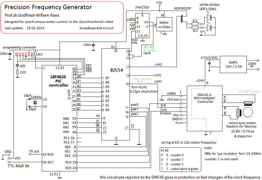
- 31.01.2012: As an alternative to using a dsPIC for the tuning motor, it
appears to be perfectly possible to use an Intel programmable 16-bit timer
chip programmed by an ordinary 18F series PIC controller with an 8-bit data
bus. Such an approach leads to following schematic:
 In the PIC firmware, a lookup table can be used for the note/frequency correspondences,
pitch bend is easy to implement and the variable phase relation between the
two frequency outputs (90 to 120 degrees) requires only a single timer in
the PIC. Even PWM would be possible by using the enable pins on the high and
low side drivers as PWM inputs. The high frequency PWM can be easily generated
in the PIC. The 18F4620 was selected in this design for it is equiped with
a full 8-bit bidirectional dataport. The 82C54 timer chip is an oldy, but
still very usefull and versatile. Have a look at the datasheet for an overview
of the many different timing functions it can fullfill. Here we have to operate
it in mode 3, as a square wave generator. The gates will be used to realize
the required phase shifts between the output waves. The disadvantage of this
circuit is that the motor is actually steered with square waves instead of
sines. This may cause heating as well as audible artefacts.
In the PIC firmware, a lookup table can be used for the note/frequency correspondences,
pitch bend is easy to implement and the variable phase relation between the
two frequency outputs (90 to 120 degrees) requires only a single timer in
the PIC. Even PWM would be possible by using the enable pins on the high and
low side drivers as PWM inputs. The high frequency PWM can be easily generated
in the PIC. The 18F4620 was selected in this design for it is equiped with
a full 8-bit bidirectional dataport. The 82C54 timer chip is an oldy, but
still very usefull and versatile. Have a look at the datasheet for an overview
of the many different timing functions it can fullfill. Here we have to operate
it in mode 3, as a square wave generator. The gates will be used to realize
the required phase shifts between the output waves. The disadvantage of this
circuit is that the motor is actually steered with square waves instead of
sines. This may cause heating as well as audible artefacts.
- 01.02.2012: Further design work on the synchronous string driver. Start
soldering work on a breadboard for this circuit. It ought to fit, with the
power mosfets, on a eurocard sized board.
- 02.02.2012: Version 1.0 of the firmware ready. Hardware debug of the breadboard
can go on. Wiring bug discovered pin 15,16 instead of 16,17 connected to the
PWM outputs. Clock and divider circuits work fine. We could also take provisions
to connect the speed sensor and set up a PID in the firmware. The Namur type
sensor can be connected to the A0 input, as we did a few years ago for the
vibi motor control.
- 03.02.2012: Couldn't get the Intel counters to work... bug found: databus
is reversed in the hardware. So now we will have to flip all bits in the software...
We can use the REV instruction.
- 04.02.2012: Now all seems to work fine. Examination of the output signals
using the Tektronix multichannel scope (TPS2024) . The phase shift is exactly
90 degrees now, but can easily be changed in the firmware. Period update limitations
will restrict the speed wherewith new notes can be played. We will have to
see whether this, or rather motor inertia is the largest limiting factor in
speed of pitch adjustment in the plucker motor. Telling from the firmware
tests, notes cannot change at a faster rate than about four per second. Here
is a view on the breadboarded prototype circuit:
 There is still some place left for the sensor input as well as for some power
LED's...
There is still some place left for the sensor input as well as for some power
LED's...
- 05.02.2012: By way of experiment, string replaced with a twisted steel-cable
as used for bicycle brakes. The sound is not very brilliant, but flexibility
is reasonably good. Pitch-bend implemented in the firmware for the synchronous
motor: this should allow phasing effects. Pitch bend will be reset on every
new and different note played. Firmware version 1.2 now. Precize note added
to the midi implementation table under the heading pitch bend. The pitch bend
range is -64 cents to + 63 cents, in exact cents units. All signals and conditions
checked on the Tektronix TPS2024 oscilloscope.
- 06-09.02.2012: further tests with the synchro motor control. We cannot get
it to rotate properly sofar. Design of PC boards using the manual design and
etching proces.
- 10.02.2012: Bypass caps added in circuit as well as protection diodes. At
some point the timer chip got bloody hot, not a normal condition... Some latch-up
occurs, but only under load conditions.
- 11.02.2012: Further testing and code development.
- 12.02.2012: Motor rechecked with 50Hz on 10V with a 6uF capacitor for phase
shift. Indeed this works. There must be something going wrong with the H-bridges
in the circuit.
- 13.02.2012: Hardware test and repair: upper IR2104 fused. Diode gone. Timer
(section for counter1) burned out... It seems that our frequencies are way
too low for the driver to work. It's better with 10k between the ' 30V power
and pin 8 of the IR2104. This cancels the bootstrap circuitry in the driver
chip. Firmware modified to make debugging possible in the lab without midi
setup.
- 14.02.2012: Without a load, the circuit does not work. It seems the +15Vref.
voltage must be on pin 6. Adding two preload resistors could be the cure.
- 15.02.2012: The IR2104, contrary to the promisses in the datasheet, is not
at all an easy chip to use. Moreover, it shows dangerous behavior when things
go wrong: the clock/pwm inputs for instance get the full Vcc voltage on failures,
leading to a burn out of the driving TTL totem pole output (in this case the
82C54). It does not perform well with non-PWM low frequency inputs, as the
bootstrap circuitry cannot keep the gate of the upper mosfet high for longer
than about 20ms, using a 820nF bootstrap capacitor. So we cannot advise its
use when it is required to allow the input frequency to go all the way down
to 0 Hz. This is a problem in motor drive applications.
- 16.02.2012: and again, the circuit blew up: smoke stacks and both IR2104
high side drivers burned out... Looks like we will have to redesign the circuit
completely. Maybe we should try using a Nanotech stepper controller instead.
In principle we can still use the same PIC firmware steering the intel timer,
but greatly simplified as we do not need to generate a 90 degree shifted signal
anymore.
- 17.02.2012: Firmware rewritten to implement the required controls for the
Nanotech controller. The circuit now becomes:
 If we use single stepping mode, we need 4 clocks for one revolution, thus
the clock frequency should become 2MHz. Timing resolution goes up to 0.5us.
If we use single stepping mode, we need 4 clocks for one revolution, thus
the clock frequency should become 2MHz. Timing resolution goes up to 0.5us.
- 25.02.2012: First working experiments with the plucking driver. It works,
but it seems we need a 4MHz clock. This seems to indicate 8 steps per revolution.
Further experiments required. At the original 7Hz frequency, the motor stutters
without rotating. Extra cooling will be required for the SMC42-2 driver, since
we had to remove the fan for it's way too noisy. An new problem arises: we
get an audible noise from the motor...
- 26.02.2012: Clock frequency changed to 4MHz. Motor turns now o.k., but speed
changes are very slow. This is probably only due to the motor inertia. Maybe
it could be improved in the firmware, by applying glissandi to the motor frequency.
Two of the pluckers broke off. The sound is quite good and even very loud!
The motor controller goes in thermal protection easily. The 4.7mF cap on the
power supply seems mandatory.
- 27.02.2012: The nasty problem with the Nanotec SMC42-2 controller is that
whenever it goes into protection mode, there is no way to reset it other than
powercycling it completely. Maybe we have to look for a more intelligent motor
controller, with build-in ramping and braking.
- 01.03.2012: IB106 controller under consideration. This is the type used
for <Rotomoton>. Research into useable materials for the pluckers.
- 04.03.2012: The mimimum current for the IB106 controller is with it's 2A
too high it seems, but didn't seem to cause any trouble. An IB104 controller
would be more appropriate, but we did not have one in stock. The schematic
now becomes:
- 05.03.2012: Rewriting the firmware for the plucker motor driver.
- 06.03.2012: Further tests and measurements on the plucker motor driver hardware.
Measurement confirmations: the motor indeed needs 8 clocks per revolution.
So for the highest note (87 in midi), we have a clock frequency of 995.5Hz
leading to a motor speed of 124Hz, equivalent to 7466rpm. This is about 50%
above the rating for the motor. For the lowest note (midi 39), we have a clock
frequency of 62Hz and a motor speed of 7.75Hz (=465rpm). Note that the frequency
of the sensor signal now exactly follows the motor clock frequency, for the
sensor wheel has 8 protruding steel pins. Motor frequency thus is sensor frequency
divided by eight. The frequency used to drive the stroboscope is half of the
motor clock frequency. Since the motor does not show any signs of warm up,
the current can safely be increased, by increasing the value of the current
sense resistor on the motor controller.
- 07.03.2012: Braking on slowdown implemented by reversing the direction of
rotation of the motor in the PIC firmware. Stroboscope clock increased to
2MHz. Ramp-up implemented in the firmware. Voltage over the motor coils is
now ca. 6.4Vac for note 39 rising to 17Vac for note 87. We could add current
regulation to get higher voltages at low frequencies using an Optor circuit
parallel over the current setting resistor on the motorcontroller. Source
code for the firmware renamed to SYNMotor3.bas,
just to make sure we preserve earlier versions.
- 08.03.2012: The firmware for the plucker seems to perform reasonably well
now. Handling of frequency measurement from the sensor is still to be implemented.
Further experimental work on the plucking plectrums themselves. Nylon string
wire (pieces of guitar B-strings, 0.8 mm thick) clamped in the M4 threads
is the first thing to be tried out. To do this really well, we would need
a subminiature lathe though. A practical test revealed quickly that 0.8mm
is too thin for a good sound. Also, the pluckers get permanently bend, leading
to problems on reversal of direction of rotation. So we redrilled the nylon
M4 threaded rods to accept 1mm thick short pieces of nylon string (guitar
G string).
- 09.03.2012: And, indeed, it does work! The concept gets proven, the sound
is very bowed-string like. Yet, as could be predicted, it will never be a
really fast instrument. Silonex optor added in circuit for dynamic current
regulation on the IB106 motor controller.
- 10.03.2012-01.06.2012: Could not even find a time slot free to continue
work on Synchrochord due to academic obligations and administration tasks
for the Logos Foundation... Hoping to get back in a few days...
- 27.07.2012: Synchrochord development taken up again. Workshop laptop configured
for experiments: Sony Vaio from 2000, running Win2000 NT, but still working
fine.
- 28.07.2012: Re-studying the firmware developed sofar... Upper bridge grinded
out and lowered such as to reduce the force required to push the string against
the frets. About 1 mm between the string and the uppermost fret seems adequate.
This was a tremendous improvement!
- 29.07.2012: Continued testing and research.
- 30.07.2012: Design and experiments with the damper mechanism. There is no
real need to use a softshift solenoid here as the only thing we need to control
is the force of the damper against the string and this is a function of coil
voltage.
- 31.07.2012: Finishing work on damper mechanism.
 First tentative
mounting in the actual robot:
First tentative
mounting in the actual robot: 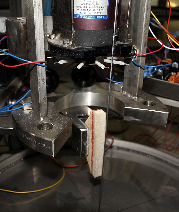 The problem now is that we do not have space enough for the mounting of the
e-driver mechanism. Between damper and exciter is possible, but makes servicing
a real hell. Selection of a suitable connector for the string driver assembly
to the different boards. Must be a single connector such that the mechanism
can easily be taken out for servicing. We decided to go for an almost antique
12-pole connector as used on Kodak carrousel slide projectors. We have plenty
of females in stock, but almost no males anymore. We used the same style with
success in our <Korn> robot. (Korn has a 16-pole connector though).
The wiring became:
The problem now is that we do not have space enough for the mounting of the
e-driver mechanism. Between damper and exciter is possible, but makes servicing
a real hell. Selection of a suitable connector for the string driver assembly
to the different boards. Must be a single connector such that the mechanism
can easily be taken out for servicing. We decided to go for an almost antique
12-pole connector as used on Kodak carrousel slide projectors. We have plenty
of females in stock, but almost no males anymore. We used the same style with
success in our <Korn> robot. (Korn has a 16-pole connector though).
The wiring became: 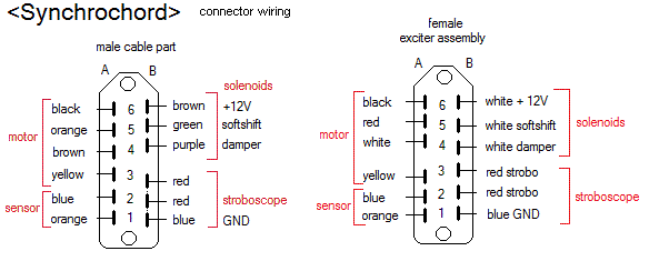
- 01.08.2012: Finalisation of the wiring of the exciter assembly to the different
controller boards. Hardware testing. The mains power wiring is still left
to be done. Firmware for Midihub Pic upgraded to version 1.2 and flashed.
Damper testing going on. Since we run out of multistranded mounting wire,
we ordered a new set of coils from Farnell.
- 02.08.2012: Signal timing diagram with midi implementation drawn out:
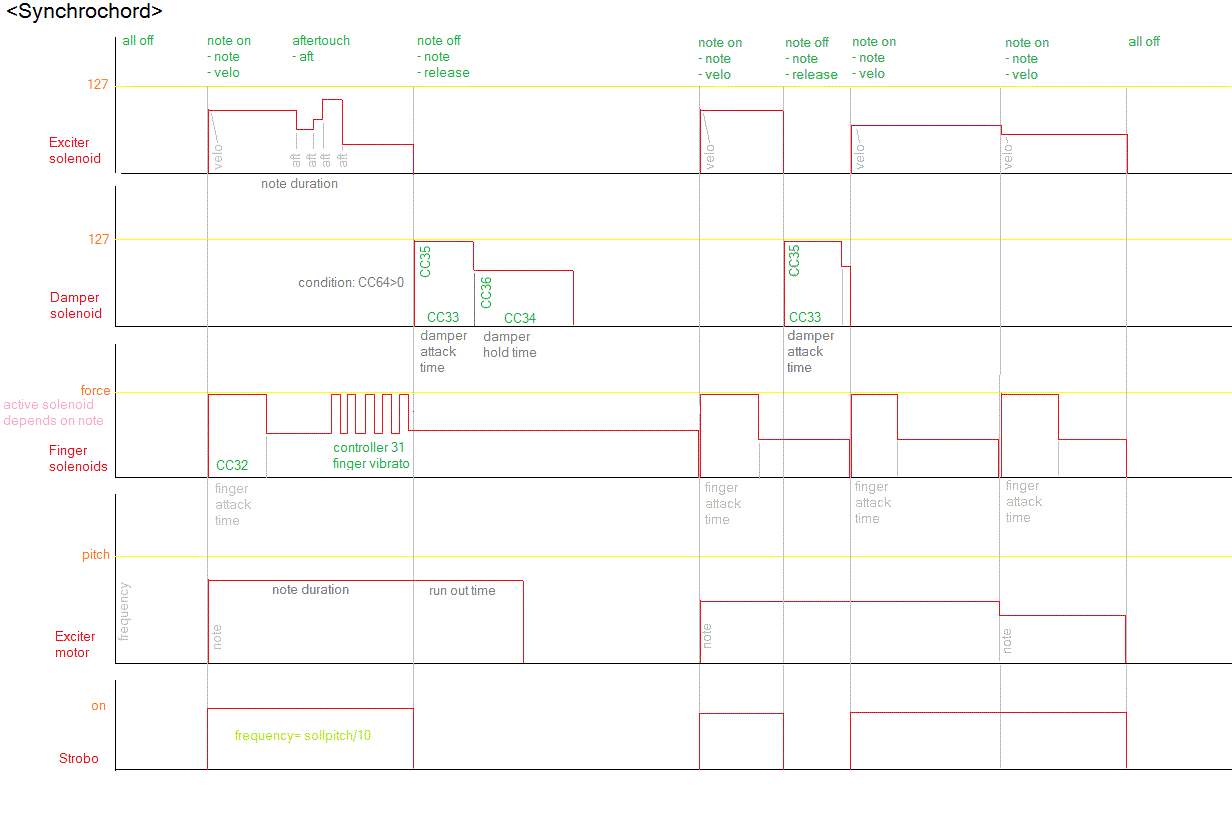 Note that the stroboscope strictly follows the sounding of the string. It
will flash whenever a note-on command is received. The flashing speed corresponds
to the pitch the string is supposed to sound. Thus slip occuring on note changes
is clearly visible by watching the exciter spindle. Midihub firmware upgraded
to version 1.3 now. GMT test code adapted accordingly. Test results: attack
time for dampers can be increased. We need more torque on the exciter motor.
We have trouble with hysteresis on the softshift solenoid. Maybe we can add
a small return spring here.
Note that the stroboscope strictly follows the sounding of the string. It
will flash whenever a note-on command is received. The flashing speed corresponds
to the pitch the string is supposed to sound. Thus slip occuring on note changes
is clearly visible by watching the exciter spindle. Midihub firmware upgraded
to version 1.3 now. GMT test code adapted accordingly. Test results: attack
time for dampers can be increased. We need more torque on the exciter motor.
We have trouble with hysteresis on the softshift solenoid. Maybe we can add
a small return spring here.
- 03.08.2012: Midi implementation for all notes off and power down checked
and corrected in the PIC firmware. Power down (controller 66) should reset
all controllers to their startup default values, whereas all notes off (controller
123) should just do what it says without modification of any controllers.
Synchrochord plays it's first sort of music now. However, there is still a
lot to be improved. To improve leakage currents stemming from the 48V SMPS
power supply, we now feed this power supply from the unused 115V winding on
the separation transformer. This way it becomes fully floating with respect
to mains ground and voltage. New SMPS power supply ordered from Farnell: TDK
Lambda LS100-48.
- 04.08.2012: Fine adjustment of damping mechanism, fingers and frets.
- 05.08.2012: Bounce back noise from finger solenoids needs to be remedied.
We can reduce the movement traject of these solenoids with maximum 3 mm. This
would improve response time also.
- 06.08.2012: Research in frequency doubling chordophones, refering to the
Picken - Adkins article (1981) referenced in the bibliography. Damper traject
reduced by adding a felt disc. Upper part of finger solenoid assembly brought
about 4mm backwards such that the lowest note solenoids have the largest possible
force.
- 07.08.2012: Bounce back noise from the finger solenoids further silenced
with latex rubber washers punched out from flat stock material. Start construction
of adjusting plates for the finger solenoids, as they tend to slip of the
string if they are not perfectly in line with the string. We also made and
mounted trajectory limiting rubber washers on the solenoids, thicknesses ranging
from 8 mm to 4 mm. These now have the double function of silencing on bounce
back and traject limiters. The felt washers remained unchanged.
- 08.08.2012: HY240 power amp ordered from Farnell, to be used as ebow driver.
- 21.08.2012: Still waiting for delivery of the ordered driver amp... In the
meanwhile, we go on with the <Klar> project...
- 12.09.2012: Finalisation of the power wiring and the main on/off switch.
Power supply (48V) for the plucker motor mounted. <Synchrochord> although
not yet ready placed in the robot orchestra, as it can already join in the
ritual production planned for september 20th.
- 15.09.2012: Firmware version 3.0 for the plucker motor implanted.
- 16.09.2012: Synchrochord used in Namuda Study #26: Rituel. Some Robodies
pictures with Dominica Eyckmans added at the very end of this webpage. Scroll
down to see them.
- 20.09.2012: Premiere of the ritual production with the robot orchestra and
Synchrochord.
- 15.04.2013: Lecture demonstration on and with Synchrochord.
- 29.12.2022: Nederlandse beschrijving toegevoegd.
TODO list:
- Precision adjustment of frets and finger solenoids
- Velocity look-up tables in midihub pic
- find and mount a better return spring for the plucker assembly
- Program change for different fingerings in the Finger PIC firmware: Prg
0 = octaves only, PRG 1 = octaves and fifths
- Slow plucking mode in motor PIC
- Add lights
- Experiment with different string materials
- Test and debug autotune microcontroller
- Mounting snd adjustment of the e-bow mechanism.
- Mount 1/4" jack output
- Replace 4700uF elco with a higher voltage type on the 48V SMPS output. We
now have a 40V type that could explode...
EVALUATION and CRITICISM
- From a sound production point of view it would have been much better to
design the exciter mechanism with an up-down movement. With such a mechanism
it would be possible to excite the string at an optimal point for any of the
fret positions pushed. For good production of the overtones, this is mandatory.
The way we did it now, some overtones fail to speak because we happen to excite
the string at a nodal point. The weight of the exciter assembly in <Synchrochord>
is way too high to make this vertical movement possible, given the required
responsiveness..
- The surface of the soundboard ought to be twice the size we gave it now,
for a higher sound level and better bass reproduction. A titanium membrane
should be considered as well.
- An exciter wheel with a hundreth or even more plectrums, driven by a high
torque stepper running at very low speeds would be an improvement. Motor speed
changes could be much faster and more precize. Nevertheless the realisation
of <Synchochord> proves the validity of the concept of synchronously
plucking strings to obtain realistic bowed sounds.
- Synchrochord is a very suitable measuring and experimenting tool for acoustic
research into string behaviour and sound. We have used it to refine the statements
and findings with regard to frequency doubling chordophones by C.J.Adkins
and Laurence Picken.
Last update: 2022-12-29
by dr.Godfried-Willem Raes
Further reading on this topic (some in dutch):
Bibliographical references:
ROSSING, Thomas.D (editor), "The
Science of String Instruments"
- ed: Springer NY, Stanford CCRMA, 2010 ISBN 978-1-4419-7109-8
PICKEN, Laurence (editor) , Musica Asiatica 3. ed.: Oxford University Press,
London 1981, pages 19: C.J. Adkins, R.C. Williamson, J.W. Flowers, L.E.R. Picken:
Frequency-doubling chordophones.
Technical data sheet, design calculations and maintenance instructions:
Technische gegevens, ontwerpberekeningen en instrukties voor onderhoud en demontage:
Fingering lookup table:
solenoid numbering corresponds to the numbering scheme on the pulse/hold PC
board. Outputs 1 (pic pins 4,3) and 2 (pic pins 2,5) are not used for fingering
solenoids.
| Midi note |
solenoid nr. -A (octaves) |
solenoid nr. B (fifths) |
solenoid nr. (alternate) |
remarks - PIC pinning |
wire color |
board output nr |
Weidmueller pin |
| 39 |
none |
none |
none |
fundamental |
|
|
|
| 40 |
1 |
1 |
1 |
19,20 |
brown |
14 |
2 |
| 41 |
2 |
2 |
2 |
17,18 |
pink |
13 |
3 |
| 42 |
3 |
3 |
3 |
15,16 |
orange |
12 |
5 |
| 43 |
4 |
4 |
4 |
22,21 |
yellow |
11 |
6 |
| 44 |
5 |
5 |
5 |
24,23 |
green |
10 |
7 |
| 45 |
6 |
6 |
6 |
28,27 |
blue |
9 |
8 |
| 46 |
7 |
7 |
7 |
30,29 |
purple |
8 |
10 |
| 47 |
8 |
8 |
8 |
34, 33 |
grey |
7 |
11 |
| 48 |
9 |
9 |
9 |
36,35 |
white |
6 |
12 |
| 49 |
10 |
10 |
10 |
10,37 |
black |
5 |
13 |
| 50 |
11 |
11 |
11 |
8,9 |
brown |
4 |
15 |
| 51 |
12 |
12 |
none |
6,7 |
pink |
3 |
16 |
| 52 |
1 |
1 |
1 |
|
|
|
|
| 53 |
2 |
2 |
2 |
|
|
|
|
| 54 |
3 |
3 |
3 |
|
|
|
|
| 55 |
4 |
4 |
4 |
|
|
|
|
| 56 |
5 |
5 |
5 |
|
|
|
|
| 57 |
6 |
6 |
6 |
|
|
|
|
| 58 |
7 |
none |
|
|
|
|
|
| 59 |
8 |
1 |
|
|
|
|
|
| 60 |
9 |
2 |
|
|
|
|
|
| 61 |
10 |
3 |
|
|
|
|
|
| 62 |
11 |
4 |
|
|
|
|
|
| 63 |
12 |
5 |
none |
|
|
|
|
| 64 |
1 |
6 |
|
|
|
|
|
| 65 |
2 |
7 |
|
|
|
|
|
| 66 |
3 |
8 |
|
|
|
|
|
| 67 |
4 |
9 |
|
|
|
|
|
| 68 |
5 |
10 |
|
|
|
|
|
| 69 |
6 |
11 |
|
|
|
|
|
| 70 |
7 |
12 |
none |
|
|
|
|
| 71 |
8 |
1 |
|
|
|
|
|
| 72 |
9 |
2 |
|
|
|
|
|
| 73 |
10 |
3 |
|
|
|
|
|
| 74 |
11 |
4 |
|
|
|
|
|
| 75 |
12 |
5 |
|
|
|
|
|
| 76 |
1 |
6 |
|
|
|
|
|
| 77 |
2 |
7 |
|
|
|
|
|
| 78 |
3 |
8 |
|
|
|
|
|
| 79 |
4 |
9 |
|
|
|
|
|
| 80 |
5 |
10 |
|
|
|
|
|
| 81 |
6 |
11 |
|
|
|
|
|
| 82 |
7 |
12 |
none |
|
|
|
|
| 83 |
8 |
1 |
|
|
|
|
|
| 84 |
9 |
2 |
|
|
|
|
|
| 85 |
10 |
3 |
|
|
|
|
|
| 86 |
11 |
4 |
|
|
|
|
|
| 87 |
12 |
5 |
|
|
|
|
|
Detail of the circuit for pulse- and hold on these finger solenoids:
Complete circuit, including the PIC microprocessor (18F4620):
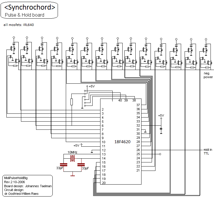 The
assembler firmware for this processor can
be found here. The hexdump usefull for people wanting to copy the design
is here. The source code
consists of two file: the
interrupt handler code and the
main code module. The Proton+ compiler was used for compilation. For programming:
use the Microchip MPLAB software.
The
assembler firmware for this processor can
be found here. The hexdump usefull for people wanting to copy the design
is here. The source code
consists of two file: the
interrupt handler code and the
main code module. The Proton+ compiler was used for compilation. For programming:
use the Microchip MPLAB software.
Midi-hub board circuit:
This board steers the damper solenoid, the plucker solenoid as well as most
of the lights.
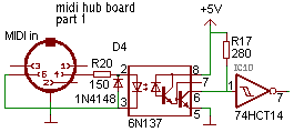
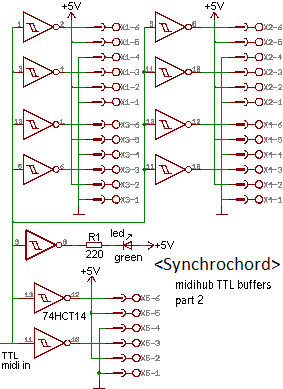
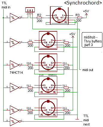

Source code for the firmware for
the hub board. If you want the hexdump.
(can be uploaded directly using MPLAB)
Tuning motor board:
Circuit notes: the input opamp is clipping by design. An improvement would
be to add an amplitude detector using a separate opamp and feed this rectified
and integrated output to the A1 input of the PIC. This way validity of frequency
measurement could be checked in the firmware against minimum amplitude conditions.
source code for the firmware for
this board. If you want the hexdump.
(Uploadable using MPLAB).
Robody pictures with Synchrochord:
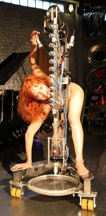
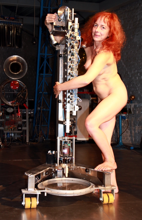

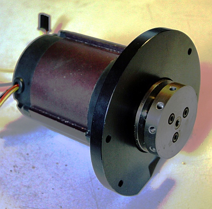 The peak to peak voltage required to drive the motor is 2 * SQR(2) * 10.8V
= 30V . We could not find a data sheet for this motor. It requires quadrature
voltages over its windings. We drive the motor using an highly overdimensioned
stepper-motor controller steered by a PIC microcontroller.
The peak to peak voltage required to drive the motor is 2 * SQR(2) * 10.8V
= 30V . We could not find a data sheet for this motor. It requires quadrature
voltages over its windings. We drive the motor using an highly overdimensioned
stepper-motor controller steered by a PIC microcontroller.
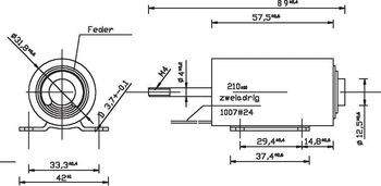 Voltage rating: 12V dc at 100% duty cycle. The DC resistance (cold) is 11
Ohm and thus the nominal current 1.09 A. This type is also used for the string
damper.
Voltage rating: 12V dc at 100% duty cycle. The DC resistance (cold) is 11
Ohm and thus the nominal current 1.09 A. This type is also used for the string
damper.