|

Research project on the development
of new tools for musical expression at the University College Ghent
School of Arts
|
|
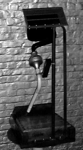
<Whisper>

an automated set of cavity resonators
Godfried-Willem RAES
2013
|
<Whisper>
This robot was designed to be very silent. It's sound production is based on
the cavity resonator, a somewhat strange device known in acoustics. In daily
life people may have run into such sound generators as they are often used as
a whistle on some water cookers. They find extensive applications in bird calls
of different kinds and in quite a few toys (rubber ducks) and simple toy instruments.
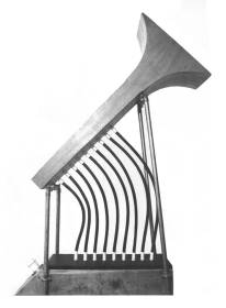
Here is a small display of bird calls from our collection, all based on the
cavity resonator: 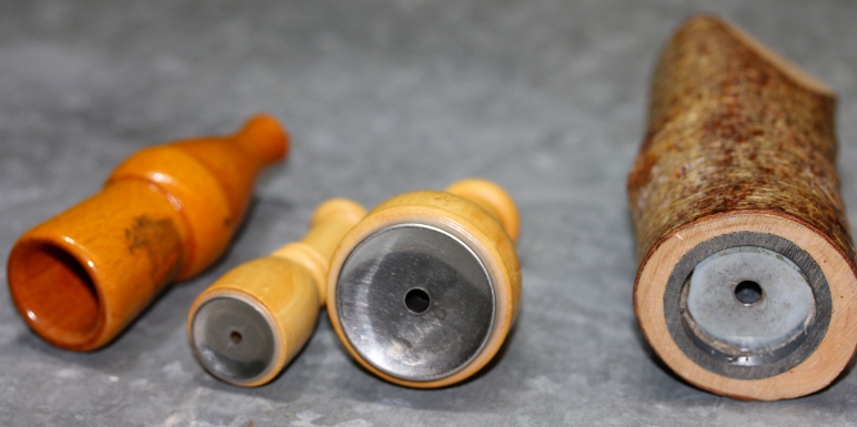 All
these are designed to be blown (or suck) with the mouth. From an acoustical
point of view cavity resonators at first sight appear to be Helmholtz resonators:
there is a cavity of air and two orifices on opposing sides of the cavity. However,
the math around them developed by Herman Helmholtz around 1860 and later refined
by Walter Rayleigh does not seem to apply here. Properly speaking a Helmholtz
resonator ought to have a single well defined resonant frequency lacking overtones,
whereas the cavity resonators under consideration here operate over a range
of more than an octave and produce a manifold of non-harmonic sounds and noises,
including multiphonics. The main reason for this behavior seems to be that our
resonators are driven by turbulent air of very low pressure and hence the dominant
sounds produced are edge tones around the orifices. It is known from organ pipes
that the frequencies of these edge tones are highly dependent on applied wind
pressure.
All
these are designed to be blown (or suck) with the mouth. From an acoustical
point of view cavity resonators at first sight appear to be Helmholtz resonators:
there is a cavity of air and two orifices on opposing sides of the cavity. However,
the math around them developed by Herman Helmholtz around 1860 and later refined
by Walter Rayleigh does not seem to apply here. Properly speaking a Helmholtz
resonator ought to have a single well defined resonant frequency lacking overtones,
whereas the cavity resonators under consideration here operate over a range
of more than an octave and produce a manifold of non-harmonic sounds and noises,
including multiphonics. The main reason for this behavior seems to be that our
resonators are driven by turbulent air of very low pressure and hence the dominant
sounds produced are edge tones around the orifices. It is known from organ pipes
that the frequencies of these edge tones are highly dependent on applied wind
pressure.
We started off by constructing a wide variety of cavity resonators. We even
tried to use obsolete CD's...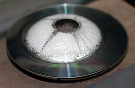 The orifice formed by the CD center hole is way too large for applications using
very low wind pressure and flow though. It works fine with a large radial compressor.
Small flat cans gave good results and had a quite wide pitch range under varying
pressure conditions:
The orifice formed by the CD center hole is way too large for applications using
very low wind pressure and flow though. It works fine with a large radial compressor.
Small flat cans gave good results and had a quite wide pitch range under varying
pressure conditions: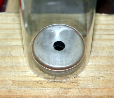 The
addition of a conical of even cylindrical secondary resonator increased the
sound level quite a bit, although it greatly influences (and limits) the pitches
obtainable. After a lot of experimentation we decided to construct these conical
resonators with the large end cut under an angle of 45 degrees, this to make
the resonant frequency less pronounced.
The
addition of a conical of even cylindrical secondary resonator increased the
sound level quite a bit, although it greatly influences (and limits) the pitches
obtainable. After a lot of experimentation we decided to construct these conical
resonators with the large end cut under an angle of 45 degrees, this to make
the resonant frequency less pronounced.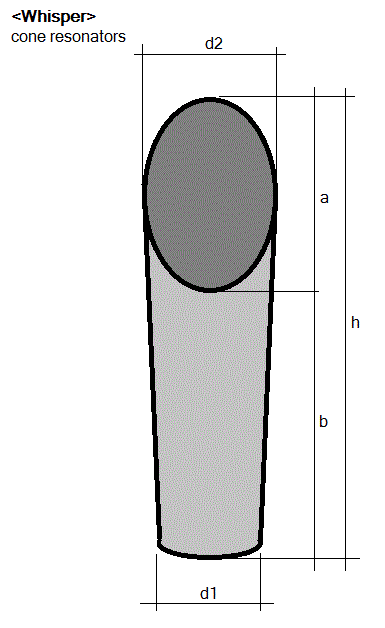 These cones were made from a tin-lead alloy as used for organ pipes. The cavity
resonators were glued inside the tapered end of the cones. We made stainless
steel flanges to mount the resonators and their cones on the windchest.
These cones were made from a tin-lead alloy as used for organ pipes. The cavity
resonators were glued inside the tapered end of the cones. We made stainless
steel flanges to mount the resonators and their cones on the windchest.
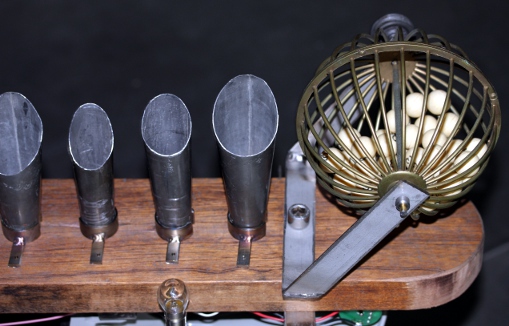
Here is a table with sizing - from low to high- for all nine cavity resonators
and the cones used in this design:
| number |
orifice diameter |
inner diameter |
inner height |
material thickness |
calculated resonance |
h |
a |
b |
d1 |
d2 |
remarks |
| 1 |
10 mm |
45 mm |
14 mm |
0.4 mm |
1103 Hz |
280 mm |
70 mm |
210 mm |
53 mm |
70 mm |
Ilford film can |
| 2 |
8.5 mm |
45 mm |
12 mm |
0.4 mm |
1095 Hz |
265 mm |
65 mm |
200 mm |
53 mm |
68 mm |
Ilford film can |
| 3 |
7 mm |
38 mm |
14 mm |
0.35 mm |
1088 Hz |
230 mm |
47 mm |
183 mm |
40 mm |
63 mm |
perfume box |
| 4 |
5 mm |
33 mm |
10 mm |
0.4 mm |
1280 Hz |
180 mm |
42 mm |
140 mm |
34 mm |
47 mm |
Adams cork grease can |
| 5 |
6.5 mm |
23 mm |
10 mm |
1.2 mm |
1945 Hz |
145 mm |
39 mm |
106 mm |
28 mm |
49.5 mm |
brass ring underneath |
| 6 |
6.5 mm |
22 mm |
8.4 mm |
1.2 mm |
2219 Hz |
116 mm |
38 mm |
78 mm |
29 mm |
47 mm |
|
| 7 |
6.5 mm |
19 mm |
5.5 mm |
1.2 mm |
3176 Hz |
114 mm |
28 mm |
86 mm |
27.5 mm |
38 mm |
|
| 8 |
6.5 mm |
16 mm |
5 mm |
1.2 mm |
3954 Hz |
110 mm |
40 mm |
70 mm |
27.5 mm |
34 mm |
|
| 9 |
8 mm |
70 mm |
18 mm |
0.5 mm |
554 Hz |
243 mm |
77 mm |
166 mm |
25 mm |
94 mm |
extra resonator mounted underneath |
The calculated resonance frequency in this table was calculated using the textbook
formula f = (v/ 2¶) SQR( r/V.L), wherein v= velocity of sound, r= surface
of the orifice, V=volume of the cavity, L= lenght of the neck, or thickness
of the material in this case with the endcorrection added. However, the observed
frequencies (without the cones mounted) from these resonators bare very little
relationship to these calculated results.
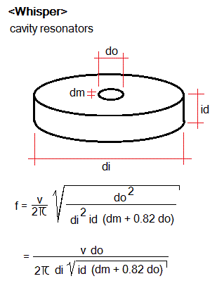
Note that when applying the formula, the surfaces of both holes have to be
added up in order to calculate the equivalent size for a single orifice do.
If we take dg as the measured diameter of a single orifice in the resonator,
then do = 2 dg / SQR(2) = dg SQR(2), or numerically: do = 1.4142 dg. The practical
calculation then becomes: 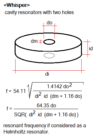 Sofar we have no sound explanation for the observed difference between calculated
and measured resonances. We might assume turbulencies play a major role here,
and maybe the velocity of sound, taken as a constant in the above calculation
cannot be considered constant. As measurements on the propagation speed of sound
in cavities and coupled cavities seemed to be in order, we performed some initial
measurements using a pair of Bruel & Kjaer measurement microphones (type
4955) and a Tektronix TDS2024 oscilloscope set up for delay measurement between
two input channels. We used an electronic metronome as pulse source, placed
as close as possible behind one of the microphones.
Sofar we have no sound explanation for the observed difference between calculated
and measured resonances. We might assume turbulencies play a major role here,
and maybe the velocity of sound, taken as a constant in the above calculation
cannot be considered constant. As measurements on the propagation speed of sound
in cavities and coupled cavities seemed to be in order, we performed some initial
measurements using a pair of Bruel & Kjaer measurement microphones (type
4955) and a Tektronix TDS2024 oscilloscope set up for delay measurement between
two input channels. We used an electronic metronome as pulse source, placed
as close as possible behind one of the microphones.
| acoustical traject (in m) |
medium (temperature: 22°C) |
delay |
velocity of sound (precision 2%) |
| 0.76 |
free air |
2.17 ms |
350 m/s |
| 0.76 |
ribbed plastic cavity tube
d1= 27mm, d2 = 34 mm
|
2.32 ms |
327 m/s |
| 1.00 |
free air |
2.85 ms |
350 m/s |
| 1.00 |
ribbed plastic cavity tube
d1 = 16mm, d2 = 20mm
|
3.03 ms |
330 m/s |
The differences are substantial, but apparently not large enough to thoroughly
explain our mystery... However, clear multiple echo's can be observed when looking
at the signals received after passing through the ribbed tubes. For the wider
tube, the echo period was measured as 4.9ms, corresponding to a pitch of 204Hz
and for the smaller one 7.4ms, or 135Hz. This indicates that the cavities indeed
work to make the tube acoustically ca. 1/4th longer than its physical length.
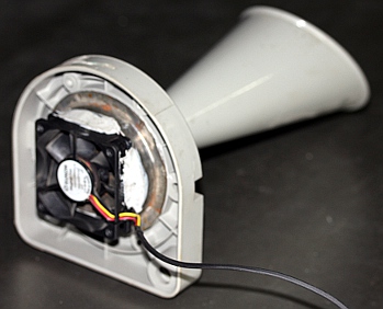
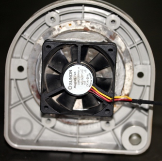
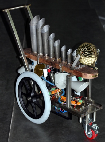
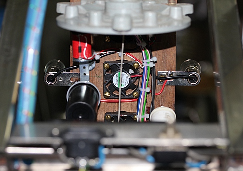
In our design for a robot based on cavity resonators, we started from a box
full of small Sunon fans used for cooling electronic components. We had collected
quite a lot of them over the years as in our designs for robotic instruments
we systematically removed fans from circuits, for they make a lot of extraneous
noise. These little fans work on a 12 V DC voltage but they easily can withstand
16 V as we found out. They typically produce turbulent air at very low pressure.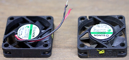 It
should be noted that this instrument works on suction wind! We have no clue
as to what explains the fact that suction wind works better, given the inherent
symmetry of the resonators. (Note: In 2015 we changed all fans for more sturdy
types, as we found them all burned one day...)
It
should be noted that this instrument works on suction wind! We have no clue
as to what explains the fact that suction wind works better, given the inherent
symmetry of the resonators. (Note: In 2015 we changed all fans for more sturdy
types, as we found them all burned one day...)
We have been using this type of acoustic sound source in quite a few of our
earlier instruments: In the 'Pneumaphone'
project, Gucumatz makes use of twelve
of them, Eurus and Tembo
use a large single resonator. In our <Thunderwood>
robot, the stormwind generator also works on this principle, though in that
case on a fairly high turbulent pressure, counting for the pretty high sound
level obtained there.
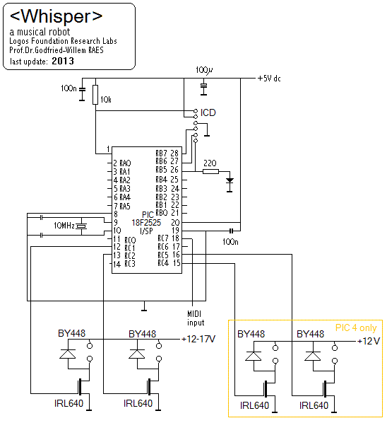
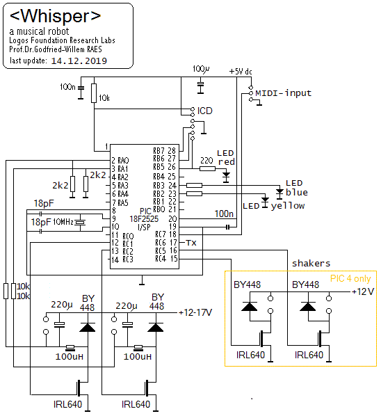
From an electronic point of view, driving 8 small DC motors is a problem we
already encountered and solved at the time when designing and building our <Sire>
robot. Hence we could use the same microcontroller board in this project. The
circuit using a single 18F2525 PIC microcontroller as well as four dual H-driver
chips can be found on the webpage describing the <Sire>
project. However, as things turned out, the firmware for that board, using only
a single PIC processor, caused audible PWM based artifacts from the fan motors.
In the <Sire> project, this came unnoticed as the sirens are pretty loud
themselves. Thus we decided to design a new PCB from scratch. As our favorite
8-bit PIC controllers have only two hardware PWM outputs on board, we used four
microprocessors to steer eight fan motors. Thus it became possible to use above-audio
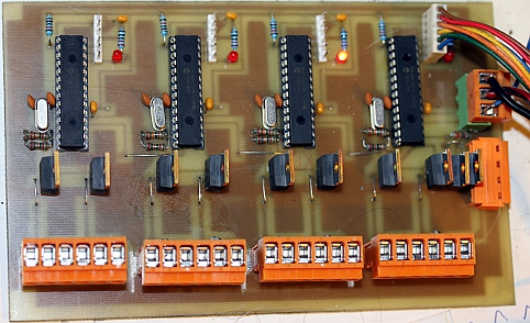
frequencies for the PWM and getting rid of audible artifacts. The circuit -repeated
four times on the PC board- , after a long time of experiments and failures,
came out like this: 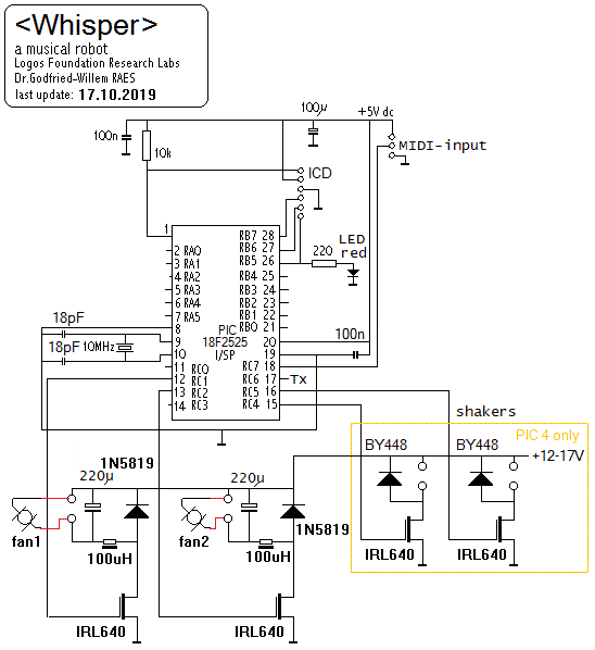
In fact the circuit is sort of a eightfold-SMPS power supply, delivering pure
DC to the fan motor, as feeding these motors with pure PWM, as we did in the
first design, proved to be detrimental to the fans. Frequent failures of the
little fans -about 20 of them went to heaven between 2013 and 2016- forced us
to reconsider the design. Apparently these fans are driven by brushless DC motors
and contain an awfull lot of circuitry inside. Driving them with PWM voltage
was not a good idea, as it ruined the electric components inside the motors.
In 2019 we redesigned the circuits such that now the motors are driven by pure
variable DC. Of course the use of fans with a PWM control lead, would also be
a solution. The design steps and adventures are fully documented in the building
diary at the end of this page. The circuit given above reflects the latest state
for the robot.
A second circuit board takes care of the PWM for the extra resonator, the rubbed
string assembly and the lights.
The rubbed string component is based on the same sound generation principles
underlying Luigi Russolo's Intonarumori. He used a crank driving a wheel over
which a piece of gut string (the tension could be controlled with a hand lever)
was led. The other side of the string being attached to a membrane connected
to an amplifying horn, a linear cone in most of his instruments. In our design
we used a metal membrane coupled to a flared cone taken from an old alarm buzzer.
The crank with wheel in the Russolo design, was replaced by a small high torque
Johnson motor powered by a variable DC voltage 
In <Whisper> we rub the string with a small dented wheel mounted directly
on the axle of the motor. Thus excitation is mostly longitudinal and passed
to the center of the amplifying membrane. Acoustically one could analyse this
as a series of approximate Dirac-pulses upon with the system reacts with its
impulse response. The repetition rate of the pulses - a function of the rotation
speed of the motor - set aside, there is no real pitch in the sound produced.
It is a highly inharmonic noise. The tension on the string changes the spectrum
greatly, but does not lead to 'tuning' of any kind. Friction increases of course
with increasing force, eventualy leading to stalling of the motor and obvious
excessive wear of the string.
The three small shakers on this robot were made from empty 35 mm film cans
filled with iron or lead granules. The shaking is activated by A.Laukhuff pallet
lifting solenoids.
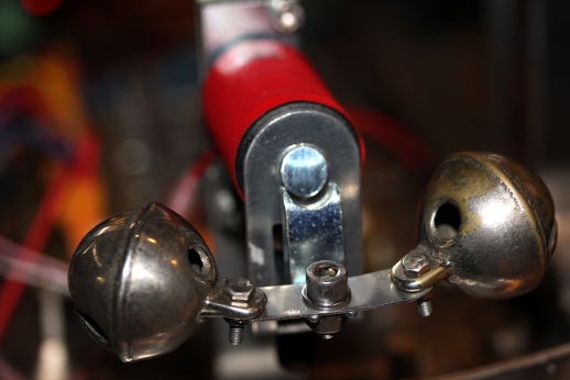
On the front of the robot, we mounted two cast bronze sleigh bells activated
by a somewhat larger Laukhuff solenoid. This was designed such that on reception
of a note on command, the armature holding the bells will resonate mechanically.
The sound of these bells is more or less defined and corresponds to midi note
104 (G#).
Midi implementation and mapping:
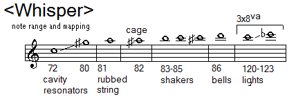
<Whisper> uses midi channel 11 (counting 0-15)
- the cavity resonators are mapped to the notes 72 to 80. The velocity byte
steers the rotation speed of the fan motors. The speed can also be modulated
using the key pressure command. Do not leave the fan motors on at full speed,
as they are then running on an overvoltage and may burn out. High velocity
values are implemented only to allow accents and bursts, not for steady sounds.
- the rubbed string is mapped on note 81, Here also, the velocity byte steers
the speed of the motor. Key pressure implemented.
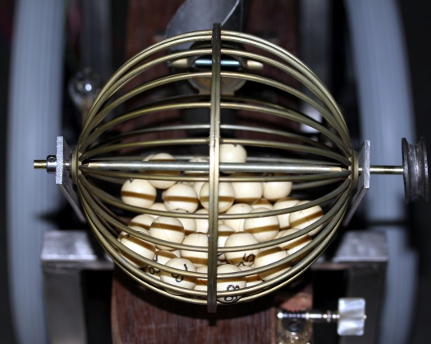
- the gambling machine (ball cage) is mapped on note 82. The velocity byte
steers the on/off frequency. With velo 127 the motor will turn continuously.
Key pressure implemented.
- the maracas (small shakers) are mapped on notes 83, 84 and 85. The velocity
byte steers the shaking speed. Key pressure is implemented to change the shaking
speed. With velocity value 127, the shakers are lifted up. With velo = 0 they
fall down again. Note that both movements make a sound.
- Note 86 steers the sleigh bells on the front. There functionality is identical
to that of the shakers.
- The tungsten lights are mapped on notes 120 to 123. The velocity byte steers
the flashing speed. With value 127 the lights will stay on. Flashing speed
can be modulated with the key pressure command.
- Controller #123 with value 0 switches all active components off.
- Controller #66 switches the robot on or off. With this controller set to
off, none of <Whisper>'s components will work.
Remark: The mapping of the velocity byte on the period of the note/event repeats
is as follows
| Velo byte |
period |
frequency |
MM tempo |
| 1 |
1500 ms |
0.66 Hz |
40 |
| 126 |
62 ms |
16 HZ |
960 |
The mapping of the pressure value accompanying the key pressure command is the
same.
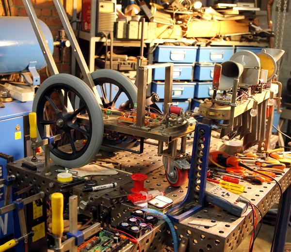
Technical specifications:
- sizes: height: 700 mm, depth 650 mm, width: 300 mm.
- flightcase sizes: height: 815 mm, depth 900 mm , width: 420 mm
- weight: 25 kg. (without flightcase)
- power: 235 V / 200 W peak. Nominal power consumption < 12 W
- tuning: Whisper is considered a non-pitched instrument.
- Loudness level: <=90dBA
- Insurance value: 8.500 Euro
Design and construction: dr.Godfried-Willem
Raes (2013)
Collaborators on the construction of this robot:
- Kristof Lauwers (GMT implementation)
- Moniek Darge, Laura Maes (requisites)
- Xavier Verhelst (application research)
Music composed for <Whisper>:
- Godfried-Willem Raes: "Whispers for <Whisper>" (2013), [6'45"]
[ Play MP3 file ]
- Godfried-Willem Raes: "Whispered Questions" (Namuda
Study #38), (2013) [10']
- Sebastian Bradt "Mestion Quarks", a solo for Whisper (2013) [3'00"]
- Kristof Lauwers "Questionable Knots" (2013), with Emilie De Vlam
and Godfried-Willem Raes [12']
- Kristof Lauwers "Whisper solo study"
Nederlands:
<Whisper>
De idee om deze robot te gaan bouwen kwam voort uit de bekommernis
om een nuttige bestemming te vinden voor een vrij grote voorraad kleine ventilatoren
die we hadden verzameld bij de bouw van vele eerdere robots. Om achtergrondlawaai
zoveel mogelijk te onderdrukken hadden we immers steeds de ingebouwde ventilatoren
in schakelende voeding, motor-kontrollers enzomeer verwijderd. Vroegere experimenten
waarbij we poogden die vertilatoren te gebruiken voor het aansturen van orgelpijpen
waren mislukt omdat de geleverde winddruk gewoonweg veel te gering was om resonantie
op te bouwen in de pijpen. Edge-tonen konden wel worden voortgebracht. Deze
observatie bracht ons op het idee klankbronnen te gebruiken die in hoofdzaak
rond dergelijke edge-tonen funktioneren, met name holte-resonators zoals we
die weervinden in vele vogel lokroepen gebruikt voor de jacht. We hadden deze
klankbronnen al eerder gebruikt: met name in het 'Pneumafoon' projekt evenals
in vroegere robots zoals <Thunderwood>, waar ze echter werden aangewend
onder een vrij grote winddruk. Voor <Whisper> wilden we het subtiele van
de edge-tonen maximaal uitbuiten. Het was van bij het begin van het opzet duidelijk
dat dit een uiterst stille robot zou gaan worden, wat niet wegneemt dat de muzikale
mogelijkheden toch vrij uitgebreid zijn. Alle negen holte-resonatoren zijn immers
individueel over een groot bereik aanstuurbaar gemaakt en de robot werd bovendien
nog voorzien van enkele extra klankbronnen..
Inspiratie puttend uit het werk van Luigi Russolo, bouwden
we een gespannen snaar aan een kant bevestigd op een stalen membraan gekoppeld
aan een korte konische hoorn. De omwikkelde snaar wordt longitudinaal aangewreven
middels een messing tandwiel aangedreven door een DC motor.
Verder werd deze robot nog voorzien van drie kleine maracas
gemaakt met twee 35mm fotoblikjes en een pillendoosje, gevuld met wat lood of
ijzergranulaat. Deze maracas worden bestuurd door kleine Laukhuff kleplichtermagneten.
Helemaal vooraan op de automaat monteerden we twee op een veerkrachtig beugeltje
bevestigde bronzen rolbellen, bestuurd door een wat grotere Laukhuff elektromagneet.
Als extra werden nog vier bestuurbare gloeidraad lampen toegevoegd.
De besturingselektronika maakt gebruik van vijf PIC mikrokontrollers
van Microchip, type 18F2525.
Omdat ons vaak wordt gevraagd hoeveel werk en tijd kruipt in,
en nodig is voor, het bouwen en ontwikkelen van een muzikale robot, hebben we
ook voor <Whisper> een beknopt bouwdagboek bijgehouden. Omdat we de bouw
tot in de laatste details graag illustreren, kan het ook voor anderen die ons
op dit pad willen volgen en/of verbeteren, van praktisch nut zijn. Dit bouwdagboek
is uitsluitend in het engels beschikbaar, gelet op de grote internationale belangstelling
voor onze projekten inzake muzikale robotika.
Construction Diary:
- 01.11.2009: First design sketches for applications for the many small 12
V fans we were left with in the lab, as we took them away from switched mode
power supplies, motor controllers and such more. The wind pressure these fans
produce is very low and definitely too low to drive any kind of organ pipe
into resonance, as we have tried out.
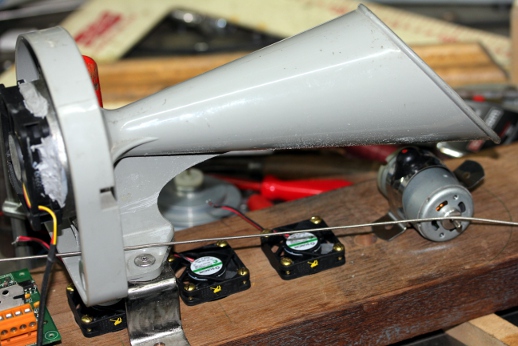
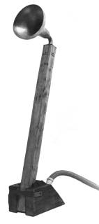
- 05.08.2013: Construction of a prototype using a square 60 mm fan mounted
to a 80 mm diameter cavity resonator with a 10 mm orifice. The resonator is
coupled to a small linear horn taken from an old alarm buzzer.
 In fact, a left-over
in our workshop from Laura Maes' construction of her 'Earwound' project.
In fact, a left-over
in our workshop from Laura Maes' construction of her 'Earwound' project.
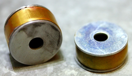
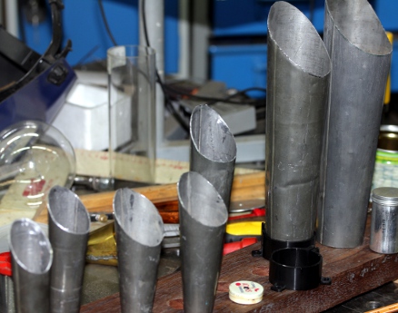
- 06.08.2013: Construction of a first set of experimental cavity resonators.
Orifices must be larger than 3 mm and smaller than 10 mm. On the following
picture two resonators are shown with 6.5 mm orifices:
 A
'bass' resonator looks like:
Here the orifices are 10 mm in diameter. The Plexiglas (polyacrylate) cylinder
works as an extra external resonator and greatly amplifies the sound output.
A
'bass' resonator looks like:
Here the orifices are 10 mm in diameter. The Plexiglas (polyacrylate) cylinder
works as an extra external resonator and greatly amplifies the sound output.
- 07.08.2013: Some six more resonators made. Start construction of a 'windchest',
although that word isn't fully applicable here. The holes drilled get a conical
shape, starting at 40mm and tapered down to 20mm where the resonators ought
to find a place. This was done to increase wind speed. Distance between the
centers of the fans is 60mm such that there is enough place for secondary
resonators pointing upwards. This 'windchest' is made from cedar wood, thickness
35 mm, 120 mm wide.
- 08.08.2013: Construction of resonators, cut from trumpet-register tin/lead
pipes from an old (18th century) church organ. In order to avoid too clearly
defined resonant frequencies, we did cut off the flared end of the cones under
an angle of 45 degrees. A few more resonators made, such that we have a variety
to select from.
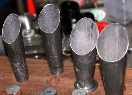
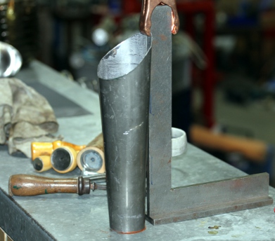
- 09.08.2013: Resonator #3 mounted in cone with brown silicone compound. Curing
takes about 24 hours. All 8 cones cut to size. Resonant frequencies of the
cavities calculated. Resonators #4-#8 mounted with brown Loctite silicone
compound. We will need electrolytic capacitor holders (clamps) for placement
of the sound generators on top of the windchest.
 Alternatively we will have to make the clamps ourselves.
- 10.08.2013: Further design work. Collecting required components for the
power supply. Start construction of the rubbed string assembly. Construction
of a mounting bridge for resonator #9 mounted underneath the windchest plate.
The rubbed string horn will be mounted on the opposing end. Experiments with
different types of motors and rubbing wheels. We have to lead the string through
the chassis of the #9 resonator.
- 11.08.2013: Experiments with different motor types for the rubbed string
component. Start design for the wheel and chassis construction. 40cm diameter
spoke wheels with polyurethane tires seem to be required here. There will
be some resemblances with the chariot made for <Bomi>, although <Whisper>
will become a 3-wheeler. Construction of the tuning peg for the string and
the hollowed part in the windchest to accomodate it. Some wood-work... that
was a while ago.
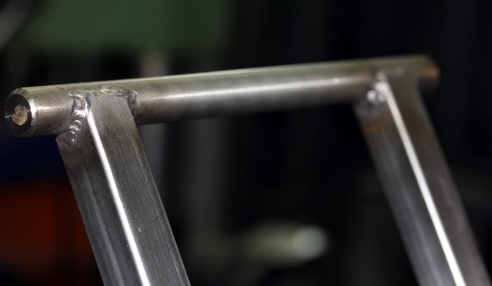
- 12.08.2013: Precise technical drawings for the wheel base to be welded in
stainless steel. Basic width of the chassis will be 220 mm , or 170 mm in
between the 25 x 25 profiles. This is just wide enough for a placement of
the midi-hub board on the backside between the large wheels.
 Construction
of the front wheel assembly, using four 20x3 pieces of tube, length 72 mm.
Mounting is with four M10 machine bolts on the 10 mm thick 100x170 mounting
plate in the front.
Construction
of the front wheel assembly, using four 20x3 pieces of tube, length 72 mm.
Mounting is with four M10 machine bolts on the 10 mm thick 100x170 mounting
plate in the front. 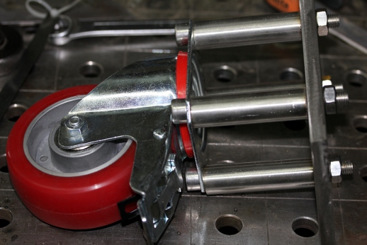
- 13.08.2013: Further construction work on the trolley. An important consideration
is that we want to keep disassembly of the wooden windchest easy and possible
without excessive tooling works. Hence the design of a pivoting 12 mm axle
through the wood combined with a bolted supporting bridge.
- 14.08.2013: New PC board designed to accomodate four 18F2525 microcontrollers,
such that we can steer the eight fans with 10 bit resolution PWM at high frequency
rates. This seemed impossible with the board used for <Sire>. This is
the circuit:
 Here
is the PCB design, done with Windows Paint... completely by hand.
Here
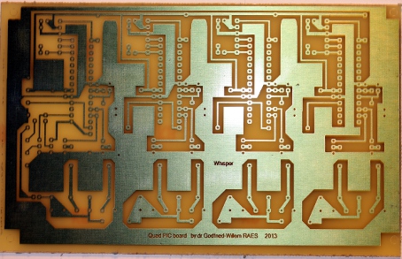
is the PCB design, done with Windows Paint... completely by hand.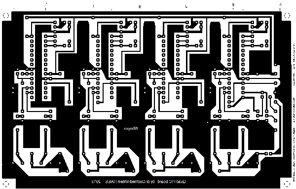 Of course the original drawing was done at a much higher resolution. Now time
for making films, developing, etching and drilling of all the holes. This
was done in a single afternoon and as the night started falling, we had all
four processors up and running on the board. Now we have to write the firmware...
Of course the original drawing was done at a much higher resolution. Now time
for making films, developing, etching and drilling of all the holes. This
was done in a single afternoon and as the night started falling, we had all
four processors up and running on the board. Now we have to write the firmware...
- 15.08.2013: A perfect working day: nobody and not even a dog around, so
efficiency raises to close to 100%... First version of the PIC firmware for
Whisper. Welding works on the trolley structure: handgrip (20 mm massive stainless
steel),
 bottom
plate with mounting holes, carying bridge for the front side of the windchest.
Test assembly. Construction of the mounting plate for the electronic circuitry.
bottom
plate with mounting holes, carying bridge for the front side of the windchest.
Test assembly. Construction of the mounting plate for the electronic circuitry.
 Building of the
power supply components (One toroidal transformer 12 V / 200 W), one 6 V /
1 A) and wiring.
Building of the
power supply components (One toroidal transformer 12 V / 200 W), one 6 V /
1 A) and wiring. 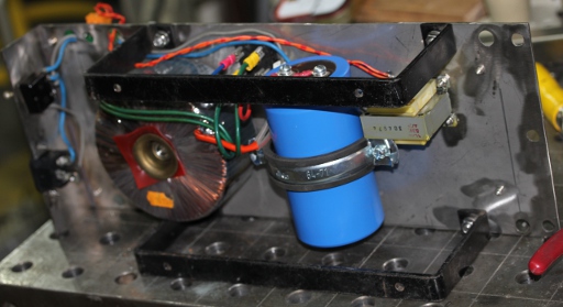 The
black stand-off pieces were added for ease of mounting and servicing. The
entire circuitry can be taken out after removal of the six M8 bolts holding
it in place on the trolley. Placement of the microprocessor boards on the
topside of the mounting plate. String membrane horn mounted with 6mm brass
woodscrews , Resonator #9 mounted. Test assembly with the wheel base.
The
black stand-off pieces were added for ease of mounting and servicing. The
entire circuitry can be taken out after removal of the six M8 bolts holding
it in place on the trolley. Placement of the microprocessor boards on the
topside of the mounting plate. String membrane horn mounted with 6mm brass
woodscrews , Resonator #9 mounted. Test assembly with the wheel base. 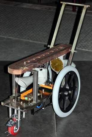 Steering
is excellent... Test of the power supplies.
Steering
is excellent... Test of the power supplies. 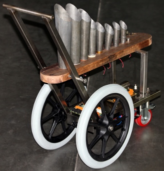 Now we get a pretty good idea of what it will look like...
- 16.08.2013: Start writing test code in GMT. These hardware tests are in
the slagwerk.exe compilation. Start construction of mounting flanges for the
pipes. We make these in stainless steel with welded-on brackets. The pipes
will be tightly epoxy-glued in these flanges.
- 17.08.2013: Finalising the works on the construction of the flanges. Start
wiring of motorized components. Resonators #1 to #8 connected using color
coded wires brown to grey. Resonator #9 coded black, the string motor, white.
Mounting of four tungsten lights: Osram 24 V / 21 W with bajonet sockets (BA15s).
As they will get at the most 17 V, these bulbs are expected to have 'eternal'
life. Two small maracas added, made from two 35 mm film cans, filled with
lead pearls. These are driven by two Laukhuff pallet lifting solenoids. In
the very front we will mount a spherical cage filled with small balls, taken
from a gambling machine.
- 18.08.2013: Construction of the motorized gambling sphere.
 In total there will be eleven motors in this robot. Two types of motor that
we have in stock proved suitable: a AEG synchronous 50 Hz motor with reduction
gears and a brushless DC Dunker motor (BG40 series). The Dunker motor has
the best potential -it even has a build-in motor controller- but posed too
many mechanical problems that we couldn't get solved on a sunday with the
shops closed... Thus we used the 230 V synchronous motor, knowing that sooner
or later this will be redesigned. Synchronous motors offer no speed control.
Turning of the wheel axle on the lathe and definitive mounting of the wheels.
Wiring of all components on the windchest finished. Thirth small maraca added
in front.
In total there will be eleven motors in this robot. Two types of motor that
we have in stock proved suitable: a AEG synchronous 50 Hz motor with reduction
gears and a brushless DC Dunker motor (BG40 series). The Dunker motor has
the best potential -it even has a build-in motor controller- but posed too
many mechanical problems that we couldn't get solved on a sunday with the
shops closed... Thus we used the 230 V synchronous motor, knowing that sooner
or later this will be redesigned. Synchronous motors offer no speed control.
Turning of the wheel axle on the lathe and definitive mounting of the wheels.
Wiring of all components on the windchest finished. Thirth small maraca added
in front.
- 19.08.2013: Soldering of the midihub board, with some modifications for
the solid state relais connected to RB4 on the PIC microcontroller. Taking
up the work of writing the firmware again... All five microcontrollers programmed
with version 1.0 of the firmware. Test code written in GMT. After finishing
the wiring, everything seems working fine! Engraved brass plate 'me fecit
logos' screwed on the front side of the windchest. Pipes fixed to windchest
with 3 x 20 brass screws. On the hub board we still haved one output free,
mapped on note 86. The scaling for the resonator fan speeds ought to be improved.
Now they even play with velocity values equal to 1, indicating we are loosing
a lot of nuance in the extremely soft sounds.
- 20.08.2013: Firmware for all PIC controllers rechecked and some bugs removed.
Now we are at version 1.1. Users manual updated. Debugging and improvement
sessions... at the end of the day we got at version 1.3 for all five microcontrollers.
- 21.08.2013: Scaling of velocity values on repetition speeds improved by
using lookup tables in the firmware. Now the range is between 0.66 Hz and
16 Hz. Start coding of a first demo piece for the <Whisper> robot.
- 22.08.2013: 'Whispers for <Whisper>' is ready and will be premiered
tonite. There is still an unsolved anomaly: the piece plays perfectly using
the Sony Vaio laptop, but if we try it from the M&M server laptop, it
fails and misses lots of midi commands... Something to sort out later. For
the premiere we used the Xi laptop and experienced no problems at all.
- 23.08.2013: Sebastian Bradt at work on a new piece for <Whisper>...
- 24.08.2013: Midi problems are unrelated to anything in the whisper robot.
We start getting more and more in trouble with the inherent transmission limitations
of the specified midi hardware. Using real diffential lines, driven by SN74176
differential bus transceivers could be a nice yet hardware compatible solution.
The absolute value of the voltage difference between the A and B outputs of
these drivers is 2.6 V. If we stick to the usual 180 to 200 Ohm current limiting
resistors on the optocoupler inputs, the current through the optocoupler LED
will be limited to 6mA and we remain within specs for MIDI hardware. These
drivers are designed to drive twisted pair cables.
- 25.08.2013: Two Epramid cylinders turned on the lathe 30 mm diameter, hole
12 mm, height 25.5 mm as distance holders for the windchest plate. Hole through
chassis and plate honed to 12 mm and 12 mm threaded rod with two bakelite
ball handles mounted. Dented belt for the gambling machine drive adjusted.
- 01.09.2013: implementation of <Whisper> in the GMT midi player.
- 10.09.2013: Writing interactive code for Whisper.
- 17.09.2013: Drawings of possible sounds to add for the missing note 86.
The front aspect also seems to ask for some redesign.
- 18.09.2013: Whisper plays a very dominant role in our 'Question Marks' production
with the robot orchestra: the premiere of Sebastian Bradt's 'Mestion Quarks',
a choreography with Kristof Lauwers and Emilie De Vlam 'Questionable Knots'
and the premiere of my own Namuda
Study #38, 'Whispered Questions', with Dominica Eyckmans.
- 20.10.2013: Failure on notes 77 and 78 for some obscure reason... debug
and repair required. Seems the fan motors have given up. Probably a user left
these on at full power for a very long time. At full power the motors get
15 V instead of the nominal 12 V they are rated for.
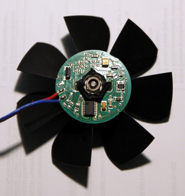
- 21.10.2013: Some alternative fans ordered from Farnell. This is how the
Sunon fans look mounted in <Whisper>:
- 22.10.2013: Test with the Pabst fan type 412J mapped on note 77: the circuit
works fine in any case. These fans are about twice as strong as the original
Sunon type. The specs are: air flow: 19m3/h, nominal voltage 12 V, voltage
range 8 to 13.5 V, noise 39 dBA, ball bearings, nominal speed 10300 rpm, service
life: 60000 h. Wind pressure: <=150 Pa. (ca. 2.4 cm H2O). Power: 2.4 W
(200 mA current at 12 V).
- 23.10.2013: Whisper repair session. Blowers for notes 77 and 78 replaced
with Pabst 412J types. PC board trace repaired. Tantalum bypass (100 uF) added
for the +5 V supply and 2.2 uF on the 15 V power supply for the blowers. This
improves EMF stemming from the PWM motor currents. All 4 PIC's on the blower
board reprogrammed. On this picture the new Pabst fans are shown, mounted
on the windchest.

- 01.11.2013: Design of a curved and polished frontal piece. Design and start
of the construction of an extra shaker sound to be mapped on note 86.
- 02.11.2013: Front part of Whisper finished. For the frontal shaking mechanism
we went for two cast bronze rolling bells mounted on a flexible metal strip,
causing mechanical resonance. The sounding pitch of these bells corresponds
to midi note 104, or high G# in the highest octave on the piano.
 New pictures shot. Here is a close up of the new front side:
 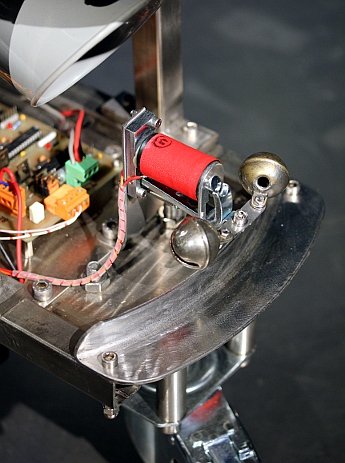 And here is the completed result: .
Firmware for the hub board rechecked and GMT test coding rewritten and upgraded
for the small implementation changes.
And here is the completed result: .
Firmware for the hub board rechecked and GMT test coding rewritten and upgraded
for the small implementation changes.
- 21.11.2013: Whisper got to play a very important role in the M&M Darkness
production with the Logos Robot Orchestra.
- 24.11.2013: Whisper transported to Vooruit for Science Day. Whisper played
eight hours continuously under radar control and activated by the audience.
At this occasion we also presented a Pecha Kucha style lecture for the kids
present.
- 06.12.2013: Lecture on Whisper for the students in the Ghent Conservatory.
- 12.12.2013: Measurements on the propagation speed of sound in cavity tubes:
indeed, sound waves propagate slower in those tubes.
- 12.09.2014: Whisper demonstrations on Odegand, Kouter Gent, animated by
Mattias Parent and Peter Van Lancker.
- 13.04.2015: Failures on the fan motors. In need of repair. Apparently all
motors burned out. Someone must have left whisper on with maximum velocity
on all notes... New fans ordered from Farnell. It's an expensive repair costing
ca. 400 Euro. We first changed the firmware in all microcontrollers such as
to limit motor voltage to 12 V. However, this way we could not obtain the
original sounds whisper was capable of producing. Maybe the new Pabst fans
are too sophisticated and do not like to be driven by PWM...
- 14.04.2015: Further research and experiments with different firmware and
different kinds of small fans...
- 15.04.2015: We found out why the new fans refuse to work under PWM conditions:
a capacitor (220 nF) across the motor solved the problem. None of the datasheets
give any information on how to use these fans in variable speed applications.
- 16.04.2015: Evaluation of the repaired robot. There are some strange behaviours
and differences between motors and parameter responses.
- 19.10.2015: Check-up on Whisper after its transport and concert at Dok19.
Works on a vocal interactive piece for Whisper to be performed by Maja Jantar.
- 05-08.11.2015: <Whisper> played four days continuously at 30CC in
Leuven, Rode Hond Festival.
- 20.07.2016: No less then 6 fan motors found to be burned out completely...
Mistreatment in the coding for the 'Haram' production? So notes 72,73,74,76,78
and 80 are in need of repair and fan replacement. This promisses to be a very
expensive repair again... Fan for note 72 (resonator 9) replaced with Pabst
8412N [80x80 mm]. We mounted a metal grid, as due to the larger size of this
fan, the blades would block against the resonator. As the scaling for this
motor needed to be different, we also modified the firmware on the hub board.
This is now Version 1.5.
- 11.12.2019: Start of a new repair session... All fans for the notes 72,73,74,76,78,79
and 80 again found to be burned. Also the black/white colored wire steering
the small shaker was found to be fully burned. The MOV over the Laukhuff coil
appeared exploded. The IRL640 Mosfet was obviously blown also. <Whisper>,
disassembled, on the servicing welding table:
- 12.12.2019: Rewrite of firmware for the midi-hub board. Now version 1.6.
Implementing 9 and 10 bit resolutions for the PWM, as well as lookup tables.
New replacement fan found for note 72 (was ebmpapst type 8412N): Dynaeon Industrial
Co., Top Motor type DF1208SH, 12V - 0.2A. Hub board firmware uploaded after
a 24h test.
- 13.12.2019: All burned fans replaced. Whisper worksheet updated. Evaluation
using a variable power supply leads to the conclusion that the Sanyo 9GV0412J301
fans perform best in this application. Mounting method for the note 72 fan
changed, using an aluminum plate with a large orifice.
- 14.12.2019: Rewriting the firmware for Q1, Q2, Q3 and Q4 pics on the motor
control boards. With lookup tables based on measurements with a variable DC
power supply. Whisper reassembled. Considering to change the motor for the
gambling machine. We already changed the dented wheel on the existing motor
for now. Tests performed: the fans do not behave according to our calculations
and measurements using a variable DC power supply. We may have to reconsider
the hardware design such as to have real DC on the motors, without PWM pulses.
Close reading of the workings of brushless DC motors revealed that there is
actually a lot of circuitry build into these fans. The paper
presented by Stephan Dunkl is most revealing and made us understand why
feeding the fans with PWM upsets the circuitry inside the motor. It should
also be made clear that measurement of the DC voltage over the fans using
a digital multimeter, is not possible. An analog instrument with a moving
coil should be used here to obtain reliable results, as it works as an integrator.
Here is a proposal for such a circuit modification:
 The 220uF cap should guarantee pure DC over the motor. The 100uH inductor
works as an 'over-the-top' step down voltage converter. The diodes ought to
be Schottky types for best performance. Obviously the inductor needs to be
capable to withstand the required fan current and the 220uF cap. should be
a low ESR type. We designed a new PCB to accomodate the circuit changes and
the newly added components. A furher step could be to measure the fan voltage
using the analog inputs on the PIC and implement a feedback regulator this
way.
The 220uF cap should guarantee pure DC over the motor. The 100uH inductor
works as an 'over-the-top' step down voltage converter. The diodes ought to
be Schottky types for best performance. Obviously the inductor needs to be
capable to withstand the required fan current and the 220uF cap. should be
a low ESR type. We designed a new PCB to accomodate the circuit changes and
the newly added components. A furher step could be to measure the fan voltage
using the analog inputs on the PIC and implement a feedback regulator this
way.
- 15.12.2019: Further calculations on possible design improvements for the
fan drivers. We disassembled a faulty fan to get a better insight in its internal
guts:
 There
is a microprocessor and the input voltage has a 47uF tantalum cap. Clearly,
driving this circuitry from PWM will lead to failure, as everytime the input
power is in the 0 state, the processor will attempt to reset... As this condition
happens 20000 times a second, no wonder it fails.
There
is a microprocessor and the input voltage has a 47uF tantalum cap. Clearly,
driving this circuitry from PWM will lead to failure, as everytime the input
power is in the 0 state, the processor will attempt to reset... As this condition
happens 20000 times a second, no wonder it fails.
- 16.12.2019: A selection of 100uH coils ordered from Farnell. Finishing designing
a new Whisper controll board. Looks like one of the newly replaced fans already
died again: note 73. Digging into the RS Components and Farnell catalogues,
we ran into the Sanyo Fan, type SanAce 9GA0412P6G001. This type has a PWM
control input, taking a 5V TTL signal as an input. Here
is the datasheet. Unfortunately, with PWM set to 0, the fan does not fully
stop. Thus, if we were to use this type, we need another way of switching
it off. After considering a high side switch, we ran into the fixed 12V voltage
regulator type KA278R12C, a
modified TO220 package with four terminals, one of them (nr.4) serving as
a disable/enable switch. This lead us to a new possible design looking like
this:
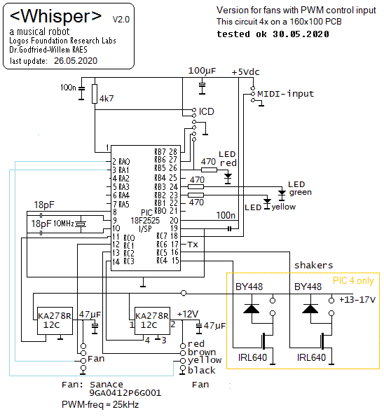 The
data sheet mentions the PWM rate as 25kHz but does not give any details as
to the allowable range.
The
data sheet mentions the PWM rate as 25kHz but does not give any details as
to the allowable range.
- 17.12.2019: A general solution to convert PWM to proportional pure DC seems
to be a circuit like this one:
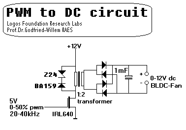 Obviously this is merely a switched mode power supply. The advantage is that
the output is fully floating. The problem is finding suitable transformers...
Obviously this is merely a switched mode power supply. The advantage is that
the output is fully floating. The problem is finding suitable transformers...
- 18.12.2019: PCB for the existing (2013) 8x PWM board retrofitted with components
for the new design, rather than producing the newly designed board. We used
Murata 100uH coils (1A, type 13R104C, Farnell order code 206-2696) and Panasonic
220uF/64V low-ESR electrolytics (Farnell order code: 250-8144). Diodes mounted
are Schottky types, 1N5819, soldered on the copper-side of the PCB with flying
leads. The circuit now became:
With this circuit, the behaviour of the fans conforms to what we specified
in the look-up tables for the PIC controllers. Here is the modified board:
 We also modified
the midi-hub board with the components steering the note 72 fan. For the rubbed
string motor, no changes are required as this is a brushed DC motor that can
be driven with pure PWM. The 'Whispers for Whisper' demo piece can now be
played again as intended. With this circuit the voltages over the fans can
be reliably measured used a digital multimeter.
We also modified
the midi-hub board with the components steering the note 72 fan. For the rubbed
string motor, no changes are required as this is a brushed DC motor that can
be driven with pure PWM. The 'Whispers for Whisper' demo piece can now be
played again as intended. With this circuit the voltages over the fans can
be reliably measured used a digital multimeter.
- 19.12.2019: The Whispers demo piece 'Whispers for Whisper' put on the program
again for tonites concert with the robot orchestra.
- 25.12.2019: Replacement of the fan for note 73 started. We replaced the
broken NMB1606 fan with a NMB1608KL type, but we probably replaced it with
one that died much earlier already...
- 26.12.2019: The NMB1608 fan for note 73 was not broken at all as we found
out, but is was mechanically blocked by the horn mounted above it. Some spacers
between the brass screws attaching the horn to the windchest plate solved
the problem.
- 22-30.03.2020: Thanks to the corona virus we found the time the construct
a sturdy flightcase for the <Whisper> robot.
- 01.04.2020: The flight case for Whisper is ready. It just needs some paint
now. Sizes are: 900 x 815 x 420.
- 19.05.2020: Failure on <Whisper> reported... Hope to get some time
to fix it, in between hospital vizits...
- 21.05.2020: something fundamental must have gone wrong, as apart from the
gambling machine, almost nothing seems to work anymore... A burned power supply
wire somewhere? Checking the quad PIC board revealed Q4 PIC to be burned out.
1N5819 diode shorted, IRL640 Mosfet for note 78 burned out. Diode replaced
with MUR460, IRL640 replaced and PIC reprogrammed and replaced. Fan for note
80 found burned out (was Pabst 422JH), as well as the fan for note 72.
- 22.05.2020: Note 80 fan replaced with Pabst 412F fan. Note 72 fan replaced
with Yate Loon D80SH12 DC fan (190mA / 12V).
- 23.05.2020: Start designing a PCB for a version using PWM-controlled fans
only. Instead of replacing almost everything in <Whisper>, we consider
to build a <Whisper-2> robot...
- 24.05.2020: PCB designed for the PWM-Fan version. The production of this
PCB was not too succesfull as the film -made with our photocopier- was not
black enough.
- 25.05.2020: PCB soldered. Some missing components ordered from Farnell.

- 26.05.2020: Firmware written for the newly made board. Waiting for the missing
components. We cannot test and evaluate without them...
- 30.05.2020: PCB completed and programmed. First tests with the Sanyo 9GA0412P6G001
fans passed. Regulation is pretty good and seems stable and reliable. It's
a pitty only, we do not have better resolution on the very low side of the
PWM range. At the other hand, this was predictable from studying the air flow
curves in datasheet.
- 01.06.2020: Construction on the lathe of some more and new cavity resonators.
- 02.06.2020: Tests and measurements using the Papst 8412N/2GHP 80x80 fan.
The usefull PWM range (using 7-bits in our midi-interface) is 11 to 127. Below
11 the fan does not start running. The
Papst datasheet does not give any information, neither with regard to
the PWM frequency nor the control characteristics.
- 20.06.2020: Whisper 2 may become a module in the <Rumo> project...
To do:
- - calculation of a parameterized model for the sound generators
- - finding and mounting a better motor for the gambling cage.
- - treatment of the wooden windchest plate.
- - research into the feasibility of the application of cavity resonators
for novel organ pipes working on very low wind pressure, whereby vibrato could
be implemented.
- - research into the construction of tuned shakers with resonators.
Last update: 2026-01-11
by Godfried-Willem Raes
Further reading on this topic:
Bibliographical references:
DUNKL, Stephan, "Design
Constraints of Small Single-Phase Permanent Magnet DC Drives for Fan Applications",
IEEE proceedings, 2015
MECHEL, F.P., "Formulas of Acoustics"
RAES, Godfried-Willem "Logos @ 50, het kloppend hart van de avant-garde
muziek in Vlaanderen" (ed.Stichting Kunstboek, Oostkamp 2018)
RAYLEIGH, John William Strutt "The Theory of Sound" (2 vols)
- ed.: Dover Publications Inc., NY, 1945, ISBN 486-60292-3
- een reprint in twee boekdelen van de originele uitgave
uit 1894. (ed.MacMillan Company)
Technical data sheet, design calculations and maintenance instructions:
Technische gegevens, ontwerpberekeningen en instrukties voor onderhoud en demontage:
- Originally: 8 small fans: 40mm x 40mm x 10mm.
. These are rated 1.0 W at 12 V, so nominal current drawn is 83 mA. Type number:
Sunon MagLev KDE1204PFV2 (Made in Taiwan, not in China as it says on the type
plate). As all fan motors burned out in 2015, we had to replace them all.
- As two of these fans (notes 77,78) gave up during operation in 2014, we
changed these fans with: Pabst 412J , Farnell order nr. 129-3489. The characteristics
of these blowers are very different than the Sunon Types. They draw 200mA
and give a much higher airflow and pressure. However, these motors also were
found burned out in 2015.
- 1 fan: 60 mm x 60 mm x 14 mm. Rated 12 V 1.4 W. Sunon GM1206PHV1-A . Burned
out 2015. Replaced with Pabst 712F. (70 mm x 15 mm)
- String motor: 6R4, Rel Bv 151 2 107/III , Rel aps 342 Tz 162 (numbers found
on the protection cap for the gears). Rel.aps.342 T1124 (number found on the
cast aluminium housing). The brand is presumably Siemens. This motor was running
too slow for our purpose.
- The string will need regular replacement as the motor will wear out the
string if used a lot. A low E string from a classical guitar will do. Other
strings can be used as well, but of course this will change the sound of the
device. Do not use excessive tension on the string, just the minimal tension
and friction such that the motor also rotates at low speeds, is perfect.
- Board wiring: Circuit
drawing:
- MidiHub board:
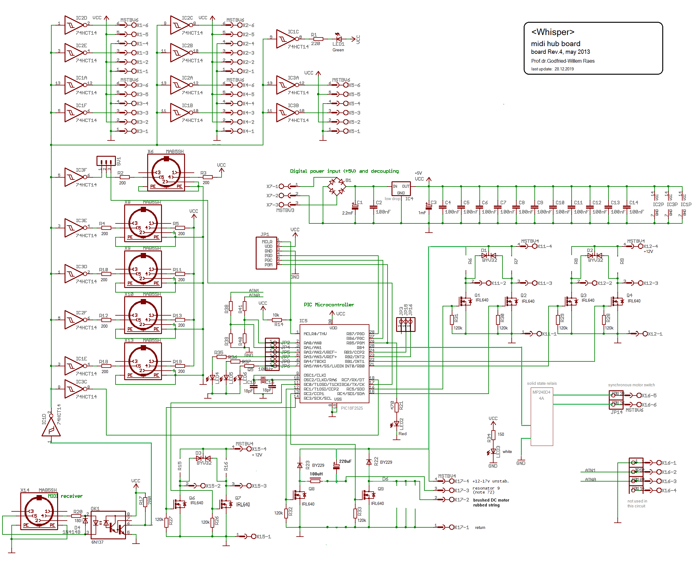
- Here are the connections for the midi-hub board:

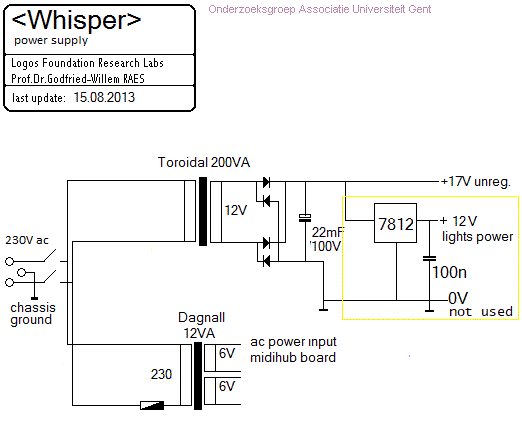
- Power supply: (Mounted on the underside of the robot trolley)
- Wheels: back wheels: 400x40 mm, Tente spoke wheels with polyurethane tires.
Front wheel: Bickle, 125 mm building heigth, wheel diameter 100 mm, width:
40 mm. Red polyurethane tire, with brake.
- Lights: 4 Osram P21W bulbs , 24V , 21W with BA15s sockets.
- Fans in use: [fan types colored red burned out]
| note |
order |
2013 |
2014 |
04/2015 |
2016 |
12/2019 |
05/2020 |
| 72 |
[9] |
Sunon GM1206PHV1-A [60x60 mm] |
id. |
Pabst 712F [70x70 mm] |
Pabst 8412N [80x80 mm] |
Dynaeon DF1208SH [80x80] |
Yate Loon D80SH12 [80x80] |
| 73 |
1 |
Sunon KDE1204PFV2 |
|
Bisonic BP4010 12H-03 |
NMB1606 |
NMB 1608KL |
NMB 1608KL |
| 74 |
2 |
Sunon KDE1204PFV2 |
|
Bisonic BP4010 12H-03 |
|
Sunon EB40201 |
Sunon EB40201 |
| 75 |
3 |
Sunon KDE1204PFV2 |
|
Pabst 412H |
Pabst 412H |
Pabst 412H |
Pabst 412H |
| 76 |
4 |
Sunon KDE1204PFV2 |
NMB 1608KL |
Pabst 412H |
|
Sanyo ACE40 EB40201 |
Sanyo ACE40 EB40201 |
| 77 |
6 |
Sunon KDE1204PFV2 |
Pabst 412J |
Pabst 412H |
Pabst 412H |
Sanyo ACE40 EB40201 |
Sanyo ACE40 EB40201 |
| 78 |
5 |
Sunon KDE1204PFV2 |
Pabst 412J |
Pabst 412J |
|
Pabst 412J |
Pabst 412J |
| 79 |
7 |
Sunon KDE1204PFV2 |
|
Pabst 412H |
Pabst 412H |
Pabst 422JH |
Pabst 422JH |
| 80 |
8 |
Sunon KDE1204PFV2 |
|
Pabst 412J |
|
Pabst 422JH |
Pabst 412F |
- note that the Pabst 8412N needed a grid to prevent the fan blades from hitting
the cavity resonator. This fan was rated for 8 - 15V DC, drawing 170mA at
12V. This fan burned out however.
- For the Dynaeon DF1208SH we made a new aluminum mounting plate, 13.12.2019.
This DF1208SH was recycled from an old PC power supply. Rated 12V - 200mA.
- Source code for the hub-board
microcontroller
- Source code for the Q1 fan motor
board
- Source code for the Q2 fan motor
board
- Source code for the Q3 fan motor
board
- Source code for the Q4 fan motor
board
For future designs -and for eventual further repairs of this Whisper robot-
we better go for the Sanyo SanAce40, type 9GA0412P6G001 types in combination
with the circuit and PCB made and designed 05.2020. Note that these fans make
use of a separate lead for PWM speed control. For note 72 the Papst 8412N/2GHP
can be used as it has a PWM input wire. The 8412N found burned out in 2016,
cannot be used! Note that for the Papst 8412N/2GHP the PWM range , using 7 bits
for MIDI compatibility, is limited to the range 11 - 127.
