|
Microtonal Musical Robot |
|
<Trumpeter>
a robotic Bb trumpet designed and made to the order of Alain Van Zeveren dr.Godfried-Willem RAES 2021 |
|
Microtonal Musical Robot |
|
<Trumpeter>
a robotic Bb trumpet designed and made to the order of Alain Van Zeveren dr.Godfried-Willem RAES 2021 |
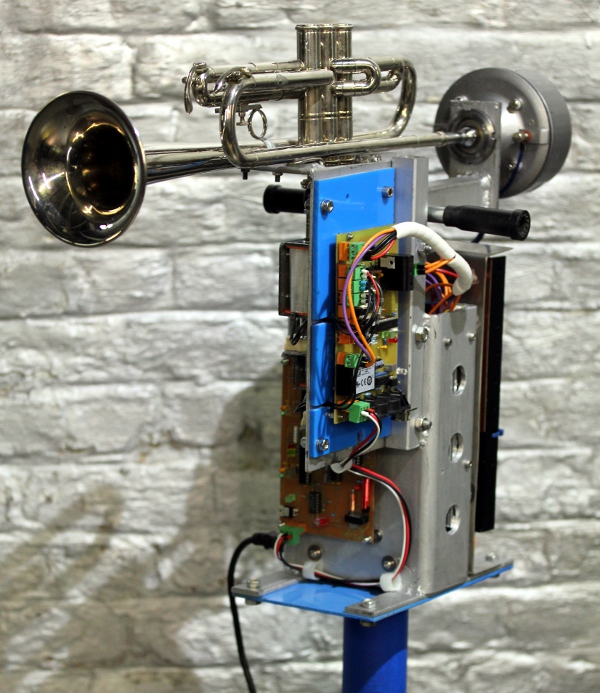
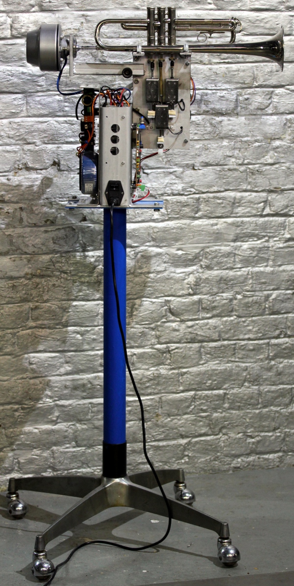
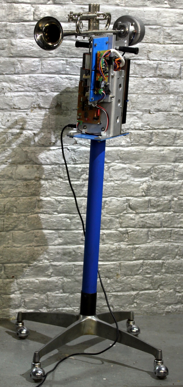
Robot: <Trumpeter>
When starting the design and construction of this musical robot, we could build further on the experiences gained through the realization of quite some automated brass instruments build since 1999: <So>, a sousaphone, <Korn>, a cornet, <Heli>, a helicon, <Bono>, a valve trombone and <Horny>, a French horn, <Bug>, a fluegelhorn and <Hunt>, a hunting horn.. This new robot, an automated trumpet, was designed and constructed to the order of Alain Van Zeveren. Musically speaking the cornet, the trumpet and the flugelhorn are very similar instruments, differing only in the timbre they produce. The flugelhorn is said to sound more mellow than the trumpet, the cornet finding a place in between. The ambitus, for Bb instruments, is the same.
Thus it made sense to start the design of this robot by examining the <Korn> and <Bug> robots and improving over them where ever possible. Main improvements we envisaged here were the sound volume, the attack characteristics and the speed of response, in particular for the valves. Again we used a membrane compressor directly coupled to the trumpet via a capillary comprised in one of the original mouthpieces that came with the instrument. The mouthpiece we first selected was one made in the Soviet Union designed specifically to facilitate sounding the highest registers of the trumpet. However, the metal alloy it was made from, caused it to explode into pieces in turning it on the lathe. That was the end of it. The alloy was clearly not heat resistent. So we reverted to a standard and completely orthodox trumpet mouthpiece. The motor driver causes resonance in the trumpet tubing, but in this case there is no unidirectional windflow through the instrument. When a note is requested from the trumpet, the firmware will calculate the optimum valve combination -including non orthodox fingerings- for the requested pitch. Thus a resonant standing wave in the instrument can be produced. Microtonal pitches are implemented such that the instrument is capable of performing quartertone music, as well as a wide range of different tunings and temperaments with great perfection. The relatively low Q-factor of the horn (compared to strings...) as an acoustic resonator renders this very well possible. The signal generated in the motor was shaped after a physical model of the air pressure waveform in the mouth cavity of a player. (Beauchamp, 1975,1980). Since there is no loop coupling from the resonator to the generator, the sound generation mechanism is a hybrid somewhere between synthetic/electronic and natural/acoustic. The advantage being that the reliability of the robot becomes very high, but this is obtained a bit at the detriment of realism, in particular with regard to the onset of the sounds, A dynamic formant filter was added using analogue electronic circuitry, in this case a pair of germanium diodes in series with a resonant LC circuit Thus the sound color will be, to a certain extend, a nonlinear function of loudness, conform to acoustic reality.
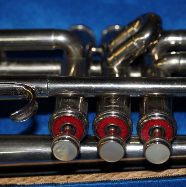
The valves are used in this instrument to tune the fundamental frequency of
the instrument. The valves can be controlled independently from the mouth driver
frequency. They are mechanically driven by unipolar push solenoids (Banggood
types made in China, to save on cost) and use the return springs provided in
the pistons in addition to the spring on the solenoids. Furthermore we mounted
the trumpet upside down such that gravity also helps improving fingering speed.
The notes that are normally produced using different valve combination, following
theory are: 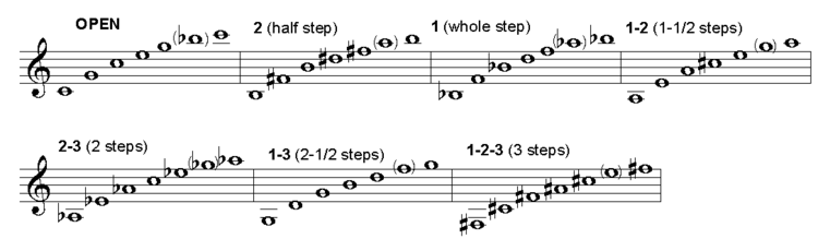 Note that this is untransposed, so in reality everything will sound a full tone
lower on a Bb instrument. However, we found out that using the valve combinations
entailed by this system, does not lead to optimum resonance in the instrument.
Thus we used the optimal valve combinations based on empirical acoustic measurement.
A deficiency we encountered in our <Korn> robot was that the buildup of
a sound pressure wave in the instrument was anticipating the valve movement.
The valves take about 10 ms to take position, thus here we delayed the driver
signal with the same amount in all cases where changes of fingering are involved.
This introduces some latency but makes the sound quite a bit more realistic,
in particular for the attack portion of the envelope. This idea was first implemented
and fully tested on the <Bug> robot.
Note that this is untransposed, so in reality everything will sound a full tone
lower on a Bb instrument. However, we found out that using the valve combinations
entailed by this system, does not lead to optimum resonance in the instrument.
Thus we used the optimal valve combinations based on empirical acoustic measurement.
A deficiency we encountered in our <Korn> robot was that the buildup of
a sound pressure wave in the instrument was anticipating the valve movement.
The valves take about 10 ms to take position, thus here we delayed the driver
signal with the same amount in all cases where changes of fingering are involved.
This introduces some latency but makes the sound quite a bit more realistic,
in particular for the attack portion of the envelope. This idea was first implemented
and fully tested on the <Bug> robot.
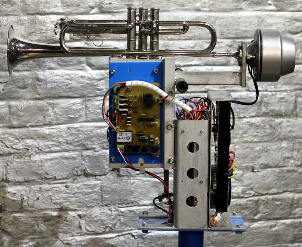
As we had to save as much as possible on cost, we dropped all movement as well as lights from the design. Thus the construction was a lot less involved than that of the <Bug> robot and we were able the finish the building project in a single -although well filled- month.
The electronic circuitry -in overview- consists of only two 'intelligent' PC-boards:
Overview: 
1. Midi-hub board: This board, using a Microchip 18F2620 controller, takes
care of the Midi I/O handling and communication as well as the control of the
three valves. The circuit for the pulse/hold function here follows a recipe
we applied nearly one hundreth times by now:  The PCB board, is a completely new design and can in principle be applied for
just about any brass instrument with up to four valves to be automated. The
sizing of the Banggood solenoids used here is:
The PCB board, is a completely new design and can in principle be applied for
just about any brass instrument with up to four valves to be automated. The
sizing of the Banggood solenoids used here is: 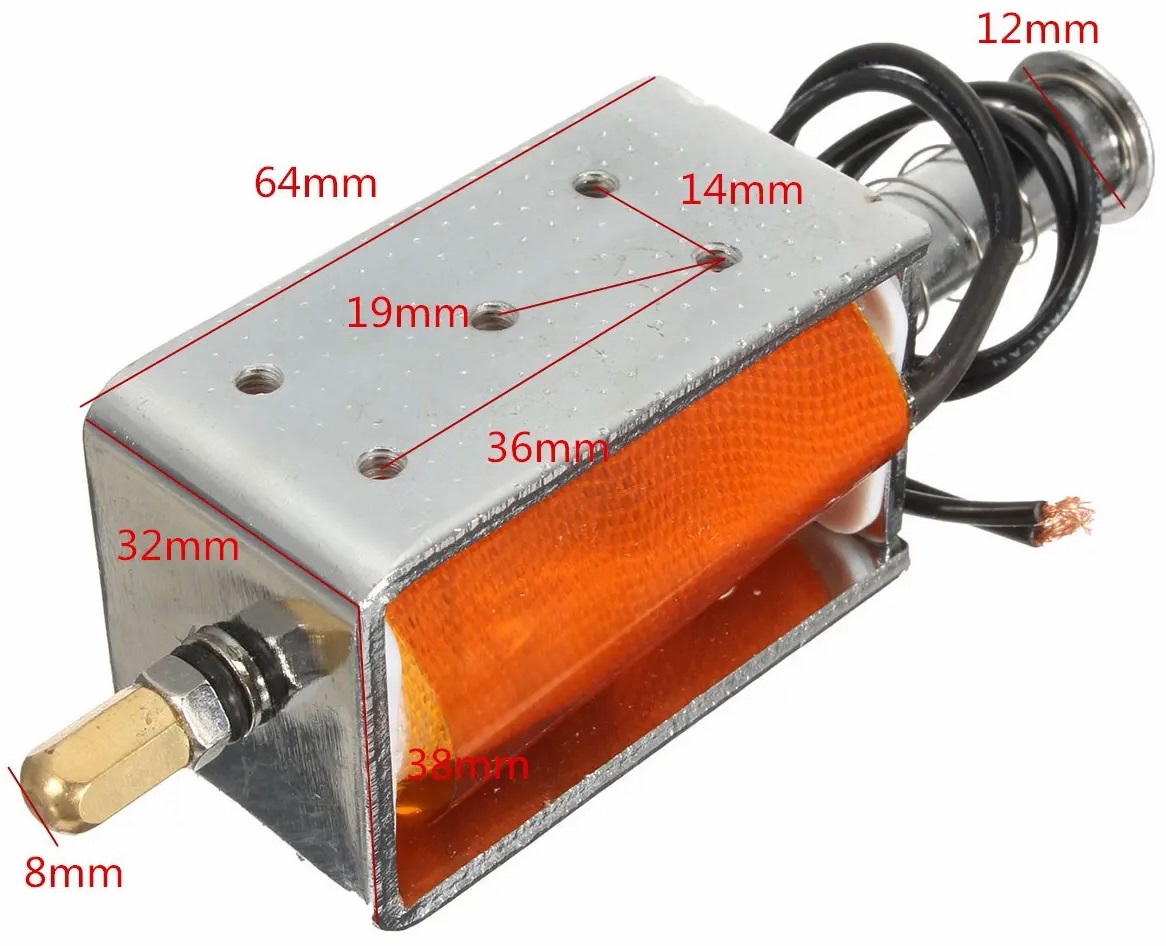
The source code for this processor is here.
The hex-dump for programming the PIC processor using MPLAB IPE is here.
2. Sound generator board: This board steers the 75 Watt motor compressor horn driver via a digital audio amplifier module. A 16-bit processor is used to generate the required waveform and two analog multipliers are used for envelope shaping and amplitude modulation. Thus we could maintain audio resolution even at the lowest soundlevels. Handling this in the full digital domain would have required a 32-bit processor. The analog dynamic formant filter also found a place on this board.
The power amp is a pure analogue design, using a high quality but by now obsolete
LM12 power opamp, in a 5-pin modified TO3 package, rated for 150 Watt:  We
designed it back in 1991 (in fact to be used as a powerfull ac source for tape-recorder
motors), but copies of it were used also for robots such as <So> and <Hunt>.
We
designed it back in 1991 (in fact to be used as a powerfull ac source for tape-recorder
motors), but copies of it were used also for robots such as <So> and <Hunt>.
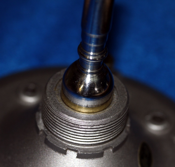
A note on the compression driver:
The longer we make the capilary and the smaller its diameter, the more will
the mechanism reveal the true resonances and timbre of the instrument driven.
However, the more we do that, the more power is required from the driver, and
obviously only drivers with finite power are available... The compression ratio
ought to be 1:50 at least. In no case should the diameter of the capilary be
larger than the smallest diameter internal in the original mouthpiece of the
instrument. A compression plate, as drawn, is not present in all makes of compression
drivers. The Padu driver we favor to use, has one. Here is a picture: 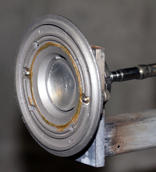 And, on the following picture it can be seen with the membrane and the voice
coil in place:
And, on the following picture it can be seen with the membrane and the voice
coil in place: 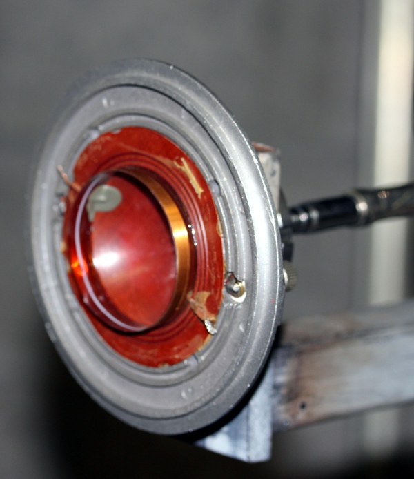 Note that
making these internal guts visible this way, is a deadly operation for the compressor.
The capton membrane with voice coil is glued to the front assembly. We did it
on a burned out compressor that we took apart for close examination.. The construction
with the compression plate helps a lot in suppressing own resonances occuring
in the compression chamber. No physical air distance inside the compressor is
larger than a half wavelength of the soundwaves corresponding to the highest
frequencies the driver can produce. Here is a frontal view on the capton membrane:
Note that
making these internal guts visible this way, is a deadly operation for the compressor.
The capton membrane with voice coil is glued to the front assembly. We did it
on a burned out compressor that we took apart for close examination.. The construction
with the compression plate helps a lot in suppressing own resonances occuring
in the compression chamber. No physical air distance inside the compressor is
larger than a half wavelength of the soundwaves corresponding to the highest
frequencies the driver can produce. Here is a frontal view on the capton membrane:
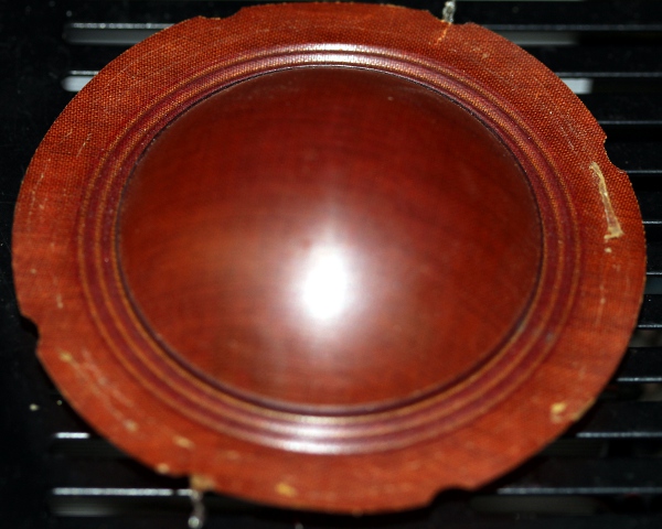 The voice coil is on the
other side.
The voice coil is on the
other side.
Power supply voltages and currents:
Midi Mapping and implementation:
Midi channel: 12 (fixed in the firmware)
Midi note range: 52 to 94. (Optimum sound in the range 66-89) Note on, velocity
is implemented and steers the level of the sustain phase in the adsr. We may
implement the pedal notes as well, in which case the range would get the extra
notes 40 to 46, with a gap between 46 and 52.
Note Off commands are required, but can be dropped for pure legato playing. Note off with release is implemented and can steer the release phase of the envelope. Note Off commands for notes that were not sounding are disregarded.
Controllers:
Controller 1: Noisiness of the sound [default = 48]
Controller 2: FM modulation delay: Delay time applied to the start of vibrato after reception of a note-on command. The range is 1 second, for a value of 127. Default is 64, corresponding to 500ms delay. It should be clear that when this controller is set to values longer than the duration of a note, no vibrato will be applied. [default = 64]
Controller 3: FM modulation depth (vibrato depth). Large values can cause audible artifacts, due to the modulation of the sampling frequency. If this controller is set to 0, the vibrato mechanism will be disabled. [default = 8]
Controller 4: FM modulation speed. (vibrato speed). This will only work if controller 3 is set to a value larger than zero. [default = 94]
Controller 5: AM modulation depth (tremolo depth) [default = 4]
Controller 6: AM modulation speed (tremolo speed) [default = 20]
Controller 7: used as a general volume controller. Note that timbre will change
as the volume is changed. On high settings, the formant frequency becomes more
dominant. [default = 90]
Controller 13: allows changes of valve fingering during sounding notes. Bit 0 corresponds to the 1/2 tone valve, bit 1 to the 1 tone valves, and bit 2 to the 3 semitone valve. Using this controller it is also possible to change the fingering for a sounding note whilst it is sounding, thus rendering some sound coloration possible without changing the actual pitch.
The table below gives all details:
Ctrl 13 Value -1/2t (valve 2) -1t (valve 1) -1 1/2t (valve 3) 0 off off off 1 on off off 2 off on off 3 on on off 4 off off on 5 on off on 6 off on on 7 on on on
Controller 15: ADSR-period [default 24]
Controller 16: used to control the duration of the attack phase in the ADSR
cycle. [default 32]
Velocity byte = attack level
Controller 17: sustain level [default = 74]
Controller 18 is used to control the duration of the decay after the attack,
the time required to reach the sustain level of the sound. [default 32]
Controller 19 steers the duration of the release decay (from sustain level to
zero) starting after reception of a note off command. Release will be canceled
or interrupted with a new note on command if such a command comes within this
time. [default 80]
The interdependencies of these controllers together with the velo byte is shown in the graph below:
CoController 20 - tuning for the trumpet. By default
equal temperament and A = 440 Hz for value 64. Acceptable values for this controller
are limited to:
Controller 25: Steers the attack force for the valve solenoids. [default =
88]
Controller 26: This controller steers the time the valves stay in their position
after reception of a note-off command. This implements some resonance in the
instrument after the excitation from the mouthpiece has stopped. It also avoids
unnecessary mechanical noise from the valves, in particular on repeated notes
or notes that can be produced with the same valve combination. [default = 32]
Controller 33: Selects different lookup tables for the fingerings. The default value 0 corresponds to our own findings in terms of optimal resonance. This lookup table differs quite a bit from the theory-book fingerings used for a Bb trumpet. Controller value 10 corresponds to the official fingering for a Bb trumpet. By setting this parameter to 9, the robot would use a lookup table as if it were a A-trumpet. With value 12, it would finger for a C-trumpet. Note that we do not treat the instrument as a transposing instrument! Acceptable value for this controller are limited to the range 0 to 12. On cold boot, this controller is always set to zero. [default = 0]
Controller 40: Selects the waveform used for the pedal tones, notes 40 to 46.
The default setting here is 6. A good alternative could be 0.
Controller 41:Selects the waveform used for the low register, notes 52 to 71.
The default setting here is 6.
Controller 42: Selects the waveform used for the medium register, notes 72 to
82 . The default setting is 1. Good alternatives are 6, 0 or 11.
Controller 43: Selects the waveforn used for the high register, notes 83 to
94. The default setting is 3. Good alternatives are 0,6,1
Waveforms implemented for these four controllers:
| 0 | Beauchamp parametric, acoustical modelling |
4 parameters: CC100, 101, 102,103 the default settings are respectively 27,83,96,110 |
| 1 | Wave_1, excitation wave | |
| 2 | Square Wave | 1 parameter: CC104, default setting is 42 |
| 3 | Wave_3, excitation wave | |
| 4 | Triangle wave |
2 parameters: CC105, CC106 default settings: 42, 85 |
| 5 | Sawtooth | |
| 6 | Wave_6, excitation wave | |
| 7 | Sine wave | added for research purposes |
| 8 | Sinx/x tophat | |
| 9 | Squared Sine | |
| 10 | Sin3 | this one tends to sound an octave lower. |
| 11 | Beauchamp textbook, acoustical modelling | |
| 12 | Pulse wave |
1 parameter: CC107 default setting: 8 |
| 13 | Asymetric sine wave |
1 parameter: CC108 default setting: 64 (with this setting, a pure sine is produced) |
| 14 | Dirty asymetric sine wave (with noise) |
2 parameters: CC109, CC110 default setting for the parameters: 20 and 64 |
Controller 66: Power on/off switch (0 = off, any other value is on). Power off
also resets all controllers to their default startup values. Also resets the
wave tables to the default startup settings.
Controller 80: Dynamic range mapping. The default is 62, resulting in a 30dB dynamic range.
| value | mapping | range |
| 0-30 | 20dB | 1:10 |
| 31-62 | 30dB | 1:50 |
| 63-94 | 40dB | 1:100 |
| 95-126 | 50dB | 1:500 |
| 127 | 60dB | 1:1000 |
Controllers 100, 101, 102, 103: parameters for waveshape parametric Beauchamp.
. This applies to Wave0. It is mandatory that Ctrl100 < Ctrl101 < Ctrl102
< Ctrl103. After reception of controller 103, the wave table will be recalculated.
Following graph describes the waveform and its parameters: 
Controller 104: parameter for setting the symmetry when waveform 2 is selected. Value 64 makes a symmetric square. Valid values are between 1 and 126.
Controllers 105 and 106: parameters for the minimum and maximum points of a
triangle wave, selectable with waveform 4. The parameters will be clear from
following waveform graph: 
Controller 107: parameter for the pulsewidth. This is waveform 12. The range for the parameter is 2 - 126. The graph illustrates the parameter:
Controller 108: parameter for setting the symmetry when waveform 13 has been selected. This is an assymmetric sinewave. Value 64 makes a symmetric sinewave. Valid values are between 1 and 126. The graph illustrates the parameter:
Controller 109: parameter for setting the symmetry when Waveform has been set to 14 (dirty assymmetric sine wave) .
Controller 110: parameter to set the level of noisiness in the waveform 14.
Controller 123: switches the sounding note off.
Pitch bend: The <Trumpeter> robot can be used in any tuning system. In the drawing below we give the coding example for a quartertone scale:
 Most good
sequencer software (such as Cakewalk or Sonar) uses the signed 14 bit format.
Note that one unit of the msb corresponds exactly to a 0.78 cent interval. To
convert fractional midi to the msb only pitchbend to apply follow following
procedure: if the fractional part is <= 0.5 then msb= 63 + (FRAC(note) *
128), if the fractional part is larger than 0.5, we should switch on the note
+ 1 and lower the pitch with msb= (1-FRAC(note)) * 128.
Note off does reset the pitch bend for the playing note! The resolution implemented
on <Trumpeter> for pitch bend (and vibrato) is limited to 1/10th of a
semitone.
Most good
sequencer software (such as Cakewalk or Sonar) uses the signed 14 bit format.
Note that one unit of the msb corresponds exactly to a 0.78 cent interval. To
convert fractional midi to the msb only pitchbend to apply follow following
procedure: if the fractional part is <= 0.5 then msb= 63 + (FRAC(note) *
128), if the fractional part is larger than 0.5, we should switch on the note
+ 1 and lower the pitch with msb= (1-FRAC(note)) * 128.
Note off does reset the pitch bend for the playing note! The resolution implemented
on <Trumpeter> for pitch bend (and vibrato) is limited to 1/10th of a
semitone.
Technical specifications:
Design, research and construction: dr.Godfried-Willem Raes (2021)
Collaborators on the construction of this robot:
Music composed for <Trumpeter>:
Some more pictures:

| Back to Main Logos page:index.html | To Godfried-Willem Raes personal homepage... | To Instrument catalogue |  |
Construction & Research Diary:
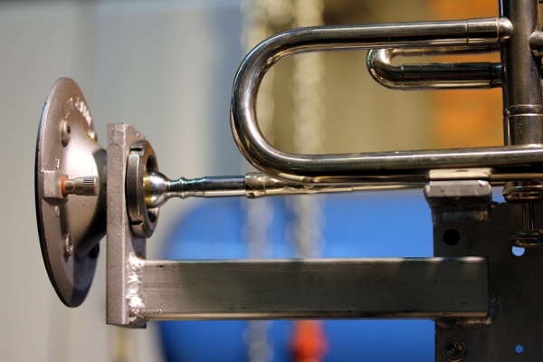
 This
is how it mounts to the robot:
This
is how it mounts to the robot: 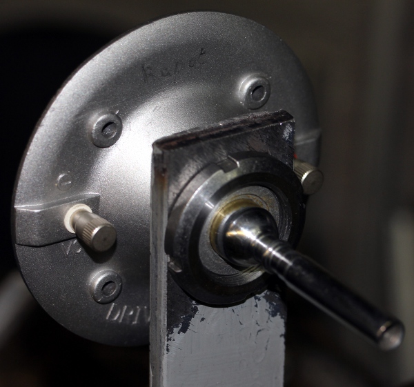
 Start welding and drilling of the mounting clamp for holding the trumpet.
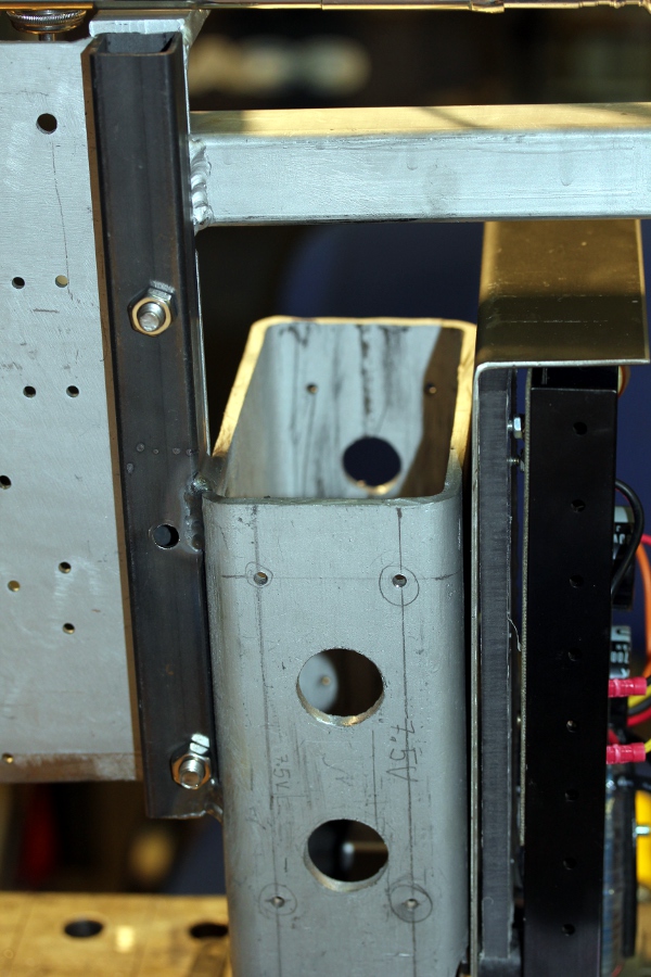
 For this construction
we use regular steel, as stainless steel is about three times more expensive.
Regular steel is also easier to weld and to work in general.It's
a pretty expensive board because we are using high precision Burr-Brown analog
multipliers here. Saving on cost at this point, leads to limitations in dynamic
range and to a much worse signal/noise ratio. First step in soldering the
components on the board:
For this construction
we use regular steel, as stainless steel is about three times more expensive.
Regular steel is also easier to weld and to work in general.It's
a pretty expensive board because we are using high precision Burr-Brown analog
multipliers here. Saving on cost at this point, leads to limitations in dynamic
range and to a much worse signal/noise ratio. First step in soldering the
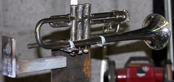
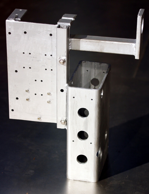
components on the board:  Further
work on the support chassis. The first thing to get done, is fixing the trumpet
in a rigid clamp without doing harm to the trumpet. Only once we get this
done, we can position the solenoids for driving the valves as well as the
compressor assembly. By the end of the day, we got most of the relevant mechanical
parts sawn out and welded together. The disadvantage of using regular steel
reveals itself again: the structure needs to be painted or sprayed... Here
are some pictures made today:
Further
work on the support chassis. The first thing to get done, is fixing the trumpet
in a rigid clamp without doing harm to the trumpet. Only once we get this
done, we can position the solenoids for driving the valves as well as the
compressor assembly. By the end of the day, we got most of the relevant mechanical
parts sawn out and welded together. The disadvantage of using regular steel
reveals itself again: the structure needs to be painted or sprayed... Here
are some pictures made today: 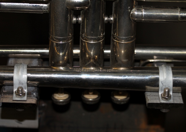
 The construction of the limiters for the anchor trajectory, serving as silencers
on fallback of the anchors as well, will be for tomorrow...
The construction of the limiters for the anchor trajectory, serving as silencers
on fallback of the anchors as well, will be for tomorrow... However,
now we have to rework the Plexiglass plate fro the solenoid driver board.
However,
now we have to rework the Plexiglass plate fro the solenoid driver board.
 The films for the PCB's
came in from Polo, so in the weekend we can proceed with some manufacturing
and electronics.
The films for the PCB's
came in from Polo, so in the weekend we can proceed with some manufacturing
and electronics.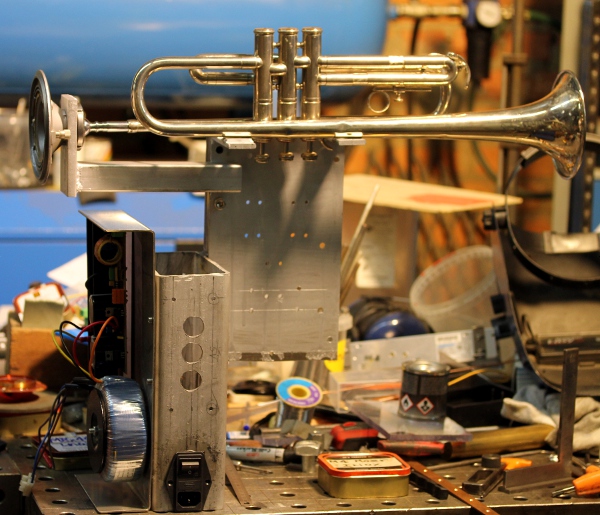
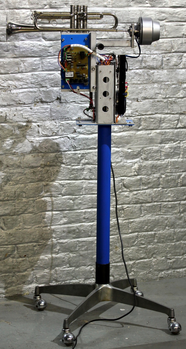
 We could even add an optional
and demountable stand using this wheelbase:
We could even add an optional
and demountable stand using this wheelbase: 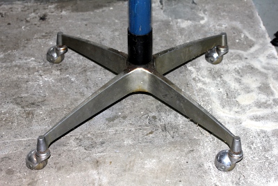 .
How much protection do we have to provide for the non-insulated heatsink on
the LM12 opamp? The heatsink metal carries the negative supply voltage for
the amplifier and should never get shorted to ground. All M4 threads for mounting
components made. All feed-through holes drilled. New layer of silverpaint
applied.
.
How much protection do we have to provide for the non-insulated heatsink on
the LM12 opamp? The heatsink metal carries the negative supply voltage for
the amplifier and should never get shorted to ground. All M4 threads for mounting
components made. All feed-through holes drilled. New layer of silverpaint
applied.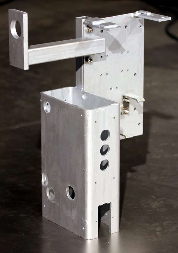
 Paint corrections and
again, assembly.
Paint corrections and
again, assembly. The
dissipation in the IRLZ34NPBF mosfet, with an Rdson=0.046 Ohm is only 0.5W
during hold. Thus no heatsink required. This mosfet is specified for 55V -
30A. For the velo-pulse mosfet, we went for a AU_IRF3710Z type. This type
is specified for 100V - 59A and its Rdson is 0.018 Ohm at Ug=10V. Thus the
dissipation of this mosfet when the velo input is on becomes 1.15W. As the
velo pulse duration is maximum 32 ms, the real dissipation will be a lot lower.
So here also, no heatsink required. Board fully populated and soldered, except
for the missing XP-Power module.
The
dissipation in the IRLZ34NPBF mosfet, with an Rdson=0.046 Ohm is only 0.5W
during hold. Thus no heatsink required. This mosfet is specified for 55V -
30A. For the velo-pulse mosfet, we went for a AU_IRF3710Z type. This type
is specified for 100V - 59A and its Rdson is 0.018 Ohm at Ug=10V. Thus the
dissipation of this mosfet when the velo input is on becomes 1.15W. As the
velo pulse duration is maximum 32 ms, the real dissipation will be a lot lower.
So here also, no heatsink required. Board fully populated and soldered, except
for the missing XP-Power module.  Just
got a message from RS-components: the modules should get here on friday...
This is the copper side:
Just
got a message from RS-components: the modules should get here on friday...
This is the copper side: 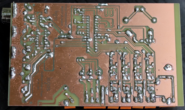 Start
coding the firmware for the midi hub and the valves. It's a bit more work
than just adapting code done for <Bug>, mainly because here we have
the valve-bits mapped on more than a single port. Start wiring of the mains
power leads and some connector.
Start
coding the firmware for the midi hub and the valves. It's a bit more work
than just adapting code done for <Bug>, mainly because here we have
the valve-bits mapped on more than a single port. Start wiring of the mains
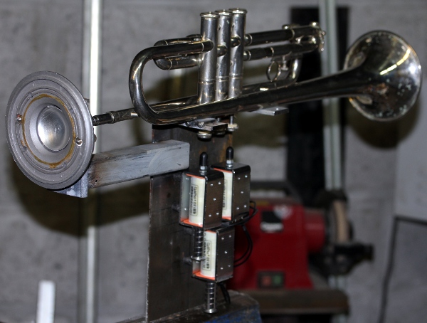
power leads and some connector.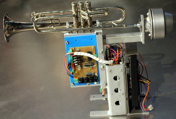 Slowly it's getting into shape.
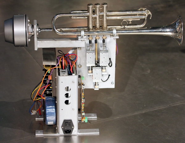 Soon we will have to make up our mind in regard of the question as to where
to hold it... The assembly is quite a bit heavier than what we first thought.
Soon we will have to make up our mind in regard of the question as to where
to hold it... The assembly is quite a bit heavier than what we first thought.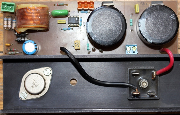 Start working on the code for the compressor driver. First preliminary version
compiled and uploaded in the PIC's. First test report: valves work fine, but
need some fine tuning and different defaults. Mounting holes still need corrections
and a lot of filing, a tedious job. Sound generation works but the power amplifier
still seems to fail: it gets very hot... There is a strong DC component on
the output... First thing to do: check the signal from the generator on the
oscilloscope and verify levels as well as DC-offset. The power supply (+37V
-0- -37V) is a bit on the high side but seems o.k. There seems to be failure
in the +/-15V supply for the multipliers and the opamps. Not the NMA0515 tiny
SMPS is in error, but one of the Epcos 100uH inductors - the one in the negative
supply lead- seems to be unconnected...
Start working on the code for the compressor driver. First preliminary version
compiled and uploaded in the PIC's. First test report: valves work fine, but
need some fine tuning and different defaults. Mounting holes still need corrections
and a lot of filing, a tedious job. Sound generation works but the power amplifier
still seems to fail: it gets very hot... There is a strong DC component on
the output... First thing to do: check the signal from the generator on the
oscilloscope and verify levels as well as DC-offset. The power supply (+37V
-0- -37V) is a bit on the high side but seems o.k. There seems to be failure
in the +/-15V supply for the multipliers and the opamps. Not the NMA0515 tiny
SMPS is in error, but one of the Epcos 100uH inductors - the one in the negative
supply lead- seems to be unconnected...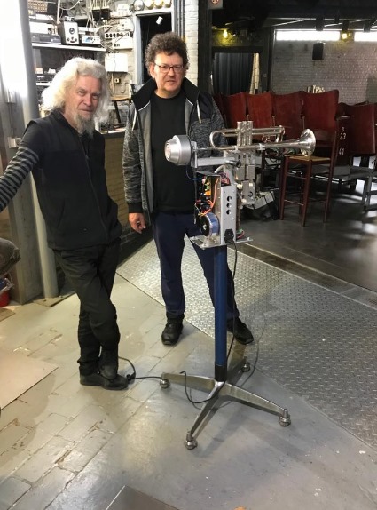
To do:
| (Terug) naar logos-projekten: | Terug naar Logos' index-pagina: | Naar Godfried-Willem Raes personal homepage... | Naar katalogus instrumenten | |
Last update: 2021-10-10 by Godfried-Willem Raes
The following information is not intended for the general public, but is essential for maintenance and servicing of the robot.
Technical drawings, specs and data sheets:
Compression driver unit: Model PADU 100, power rating 100W, impedance 16 Ohms. (Made in China) We have measured this component carefully when making <Asa> and found the impedances in function of applied frequency as follows:11.4 Ohms @ 100Hz, 23.68 Ohms @ 1kHz, 26.7 Ohms @ 10kHz and 45 Ohms @ 25kHz. The acoustic load does influence the measured impedance at 1kHz over a 1:2 range: with the mouth completely closed it measures 32.8 Ohms and with the mouth completely opened but without any resonator, 15.35 Ohms. This phenomenon does not occur for the very low neither for the very high frequencies. The measurements were performed in 2016 with our Hameg LCR meter, model HM8018. The frequency response is 100Hz to 10kHz. The thread for mounting is 1 3/8"-18 TPI.
Valve lookup tables (according to acoustic theory)
Power supply:
Circuit drawing for the valve control and MIDI hub board:
Firmware for the hub board:
PCB for this hub board designed for 3 or 4-valve brass instruments:
[scale 200%]
Power supply modules for this board:
Compressor driver board (monophonic synth with acoustical modelling):
Circuit drawing:
PCB for this circuit:  [scale:
200%]
[scale:
200%]
Current drawn by this board 310mA @ 5V supply.
Soldered board:
References:
Beauchamp, J.W. "Analysis and Synthesis of Cornet Tones Using Nonlinear Interharmonic Relationships". In: j-aes, volume 23, number 10, pages 778--795, 1975.
Beauchamp, J.W., "Analysis of Simultaneous Mouthpiece and Output Waveforms of Wind Instruments" . In: j-aes, 1980, Preprint No. 1626,
Benade, Arthur .H., "Fundamentals of Musical Acoustics". Ed.: Oxford University Press, 1976.
Fletcher, N.H. & Tarnopolsky, A. "Blowing pressure power and spectrum in trumpet playing" In: J. Acoust. Soc. Am., volume 105, number 2, part 1, 1999.
Martin, Daniel W., "Lip vibrations in a Cornet Mouthpiece", In: J.Acoust.Soc.Am. vol13 . 1942
Raes, Godfried-Willem, "Kursus Akoestiek", Ghent University College 1982/2014, Internet: http://www.logosfoundation.org/kursus/4023.html
Raes, Godfried-Willem, <Bug> an automated Fluegelhorn, 2016.
Raes, Godfried-Willem, "Expression control in musical automates", 1977/2021,
Raes, Godfried-Willem, "Logos @ 50, het kloppend hart van de avant-gardemuziek in Vlaanderen", ed. Stichting Kunstboek, 2018
Rose,Nicholas and Holloway, Damien, "Finite element modeling of brass musical instruments', in: Proceedings of Acoustics, Fremantle, Australia 2012.
Smith, Bob H., "An Investigation of the Air Chamber of Horn Type Loudspeakers", in: The Journal of the Acoustical Society of America 25, 305-312 (1953); https://doi.org/10.1121/1.1907038
Cost calculation for <Trumpeter>:
1. Parts and components
| Bb trumpet | made in GDR (German Democratic Republic) |
p.m.
|
| Steel | 2 Euro/kg |
26.00
|
| Solenoids | 3 Banggood 12V, 1.5 Ohm |
99.00
|
| Trumpet mouthpiece, Maheu | 1 |
38.00
|
| Membrane Compressor 100W | 1 (Padu driver, 1 3/8" 18TPI mounting thread) |
210.00
|
| 35 mm nut (1 3/8" - 18 TPI) | 1 (for tightening with a 35-50 mm hook wrench) |
27.00
|
| Brass staff-material | 100 mm |
3.00
|
| Soft PVC endcaps | 3 |
0.60
|
| M4 shock absorbers MF | 12 |
36.00
|
| M4 x 8 cilinder bolts | 15 |
9.50
|
| LM12 amplifier 150W sine | 1 |
150.00
|
| Mean Well SMPS 7.5V 20A | 1 |
75.00
|
| Mean Well SMPS 5V 20A | 1 |
75.00
|
| Polo, PCB-films | 2 |
50.00
|
| Mirargent, silver paint | 1 small jar |
6.80
|
| Blue polyacrylate, plexiglass | 1 piece |
2.50
|
| Spirawrap | 1 m |
1.00
|
| Wheelbase | recycled part |
p.m.
|
| Cyanoacrylate glue | 1 (Loctite 401, 3g) |
4.00
|
| PCB Hub board | 3 analog in, 4 pulse/hold outputs, 3 outs, midi-in, differential thru, TTL midi out PIC 18F2620, 5V-2A power supply module, Weidmueller connectors |
355.00
|
| PCB Generator board | 2 16 bit PIC 24EP128MC202, 4 low noise op amps, 2 Burr-Brown multipliers, Weidmueller connectors, 1% precision resistors, 5 inductors |
435.00
|
| IEC Mains power entry | Schaffner FN-372 6 (230V - 6A) with switch and fuse |
13.50
|
| Faston connectors, blue | 35, power supply wiring |
11.00
|
| Wire | 25 m, 0.75 mm2, 1.5 mm2 |
6.00
|
| Waco connectors, snap in | 2 5-contacts, 1 3-contacts |
3.00
|
| Wiring | 30 m of mounting wire in coded colors |
18.00
|
| Heatshrink tube | Polyolefine 1 m |
6.00
|
| Felt 10mm thick | for mounting and dampening |
2.00
|
| Paint | RAL5012, blue |
2.00
|
| Subtotal parts: |
1664.90
|
2. Consumables
| Cobalt 3mm drill bits | 1 |
3.50
|
| Cobalt 4mm drill bits | 1 |
3.80
|
| Cobalt 5mm drill bits | 1 |
4.00
|
| Cobalt 8mm drill bits | 1 |
9.00
|
| TIG welding materials | Argon gas and Tungsten electrodes |
10.00
|
| Cutting disks | 2 (A60 T-BF41 125 x 1.0 x 22.2 |
8.00
|
| Sanding disks and paper | 1 |
4.00
|
| TIG welding nozzle, nr.5 | 1 |
12.00
|
| Cutting oil (spray can) | 1 |
1.00
|
| Solder Pb/Sn 40/60 & leadfree | 5 m |
5.00
|
| Steel welding electrodes | 10 3.2 mm |
8.00
|
| Aceton | 0.5 l |
4.00
|
| Etching baths | Fe2Cl3 1 liter |
5.00
|
| Methanol | 0.25 l |
2.00
|
| NaOH sollution | 0.5 l |
1.00
|
| Subtotal: |
80.30
|
3. Depreciations on tools and equipment used (calculated over 1 month)
| Tool | Value | Depreciation percentage / month | |
| Tektronix TDS2024C | 3500 | 2.77% |
97.00
|
| TIG welding equipment | 2000 | 2.77% |
55.00
|
| Contimex Lathe | 2500 | 2.77% |
69.50
|
| Cobalt saw | 2800 | 2.77% |
77.50
|
| Soldering equipment | 1000 | 2.77% |
27.50
|
| Proton+ Laptop & ICD | 1800 | 2.77% |
25.00
|
| Lab power supply | 380 | 2.77% |
5.00
|
| Odin column drill | 6000 | 0.92% |
27.50
|
| Welding table | 2500 | 0.92% |
11.50
|
| Subtotal: |
395.50
|
4. Labor and design (45,-/hour)
| 02.06.2021 | 8 h |
360.00
|
| 03.06.2021 | 3 h |
135.00
|
| 04.06.2021 | 3 h |
135.00
|
| 05.06.2021 | 7 h |
315.00
|
| 06.06.2021 | 3 h |
135.00
|
| 07.06.2021 | 30' |
22.50
|
| 08.06.2021 | 30' |
22.50
|
| 09.06.2021 | 2 h |
90.00
|
| 10.06.2021 | 30' |
22.50
|
| 11.06.2021 | 4h |
180.00
|
| 12.06.2021 | 3h |
135.00
|
| 13.06.2021 | 1h |
45.00
|
| 14.06.2021 | 3 h |
135.00
|
| 15.06.2021 | 8 h |
360.00
|
| 16.06.2021 | 2 h |
90.00
|
| 18.06.2021 | 2u |
90.00
|
| 19.06.2021 | 3u |
135.00
|
| 20.06.2021 | 6u |
270.00
|
| 21.06.2021 | 8u |
360.00
|
| 22.06.2021 | 6u |
270.00
|
| 23.06.2021 | 8u |
360.00
|
| 24.06.2021 | 7h |
315.00
|
| 25.06.2021 | 9h |
405.00
|
| 28.06.2021 | 30' |
22.50
|
| Subtotal: |
4410.00
|
[EOF]