A sound pressure level meter for ultrasound
laboratory instrument for the measurement of ultrasonic power output in the frequency range 10 kHz to 100 kHz
by
dr.Godfried-Willem Raes
postdoctoral
researcher
Ghent University, Orpheus Institute & Logos Foundation
2015/2019
When it comes to sound pressure measurement, sound level meters nowadays can be found on the market at very decent prices. However, if you want to measure sound pressure in the ultrasonic range, these meters cannot be used. (1). First of all, the dbA measurement scale is without object as we are in the area of inaudible sounds. But, even the linear unfiltered scale (if dBC is available on the meter) is pretty useless as the frequency response curve rarely extends beyond 20 kHz. Of course such measurements can be carried out using Broel&Kjaer calibrated measurement microphones, but at a cost of over 12.000 Euro, this seems rather prohibitive. This project describes a simple and relatively cheap analogue meter allowing measurement of sound pressure levels in the range 10kHz up to 100kHz. The sensitivity is not as good as when using Broel&Kjaer devices, but within the range 76 dB SPL and 140 dB SPL, it performs quite well and with reasonable linearity (+/- 3dB). The circuit makes use of a MEMS microphone by Knowles Acoustics, type SPH064HT5H-1. This microphone, measuring only 3.50 x 2.65 mm and 1.0 mm thick, is omnidirectional. The acoustic port has a size of merely 0.2 mm! The datasheet is given in the notes below (2).
First design:
Circuit drawing:
The first stage, build around a precision opamp, is an amplifier with variable gain: 46 dB (200x), 26 dB(20x) or 6 dB (2x). There is a roll off of -3 dB at 80 kHz, mainly due to the limited gain-bandwidth product of the opamp. Sound pressure level at the acoustic port should not exceed 124 dB. If very high sound levels are observed, increase the distance between source and instrument. The BNC connector carries the amplified signal and is provided to connect an oscilloscope to observe clipping and waveform. The common distance for measurements in the ultrasonic range is 30 cm. At 1 m distance (the normal value for acoustic measurement) , the SPL should be expected to be ca. -10 to -12dB, provided there are no reflective walls or surfaces nearby. Ideally measurements should be performed either in open space or in an anechoic chamber.
After the amplifier the signal is sent to a true-rms conversion circuit (Analog Devices AD736) (3). The DC output of this circuit feeds the large analog VU panel meter. The optimum output voltage range for this chip is 0 to 4V, yielding a good match with the panel meter we selected. Sound pressure levels corresponding to the values read on the meter, can be deducted from the following table.
| switch position | gain | VU meter value |
SPL
|
| 0 | 46 dB | 0dB (100%) |
96 dB
|
| 0 | +3dB |
99 dB
|
|
| 0 | -20dB (10%) |
76 dB
|
|
| -20 dB | 26 dB | 0dB (100%) |
116 dB
|
| -20 dB | +3dB |
119 dB
|
|
| -20 dB | -20dB (10%) |
99 dB
|
|
| -40 dB | 6 dB | 0dB (100%) |
136 dB
|
| -40 dB | +3dB |
139 dB
|
|
| -40dB | -20dB (10%) |
119 dB
|
The table is valid for a distance between sound source and microphone of 30 cm. As a reminder, note that sound pressure goes down with the square of distance. Thus at 15 cm distance the values will be 6dB higher and and 60 cm 6 dB lower. Although the instrument is fairly insensitive to lower audio frequencies, it should go without saying that measurements ought to take place in a silent environment.
Hand drawn PCB-board for the circuit above (at 200% scale):

The MEMS microphone, an SMD component, is soldered on the component
side of the board. Soldering little wire wrap wires to this component is a really
tedious job that can only be accomplished under binoculars and using appropriate
tools . The acoustic port of the microphone is on the component side as well.
Here is a picture of the assembled board: 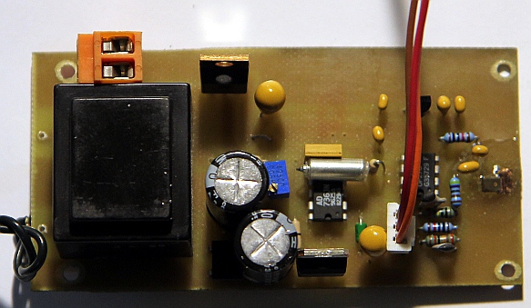 The microphone can be seen on the right side of the picture. An acoustical pipe
mounted on the cabinet allows the sound to come in and protects the microphone.
It renders the instrument more directional. This is a view on the inside of
the front panel before assembly:
The microphone can be seen on the right side of the picture. An acoustical pipe
mounted on the cabinet allows the sound to come in and protects the microphone.
It renders the instrument more directional. This is a view on the inside of
the front panel before assembly:  All components are secured to the chassis with some two component epoxy glue.
The figure-8 mains power connector is on the top side of the enclosure. The
instrument has no fuses as power consumption is very low and the small 2 x 15
V transformer is short circuit proof.
All components are secured to the chassis with some two component epoxy glue.
The figure-8 mains power connector is on the top side of the enclosure. The
instrument has no fuses as power consumption is very low and the small 2 x 15
V transformer is short circuit proof.
The entire circuit as well as the panel meter fit nicely into
an cast aluminium BIM-box. The result looks like: 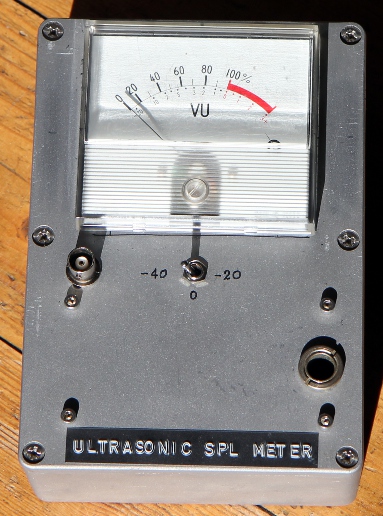
For calibration, we used a sinewave oscillator set to 10kHz connected to an audio amp and loudspeakers. We turned up the volume for a reading of 90 dBC on our normal acoustic sound level meter and thus determined the reading on our own instrument. Next we fed a 10 Vrms signal at 40 kHz to a Murata transducer for the same frequency that after the datasheet gives 90 dB SPL under these conditions and checked our own meter for conformity. Of course the resulting precision cannot exceed that of the reference meter at the one side and the precision of the Murata datasheet at the other. However, at least now we dispose of an instrument capable of doing reliable comparative measurements on ultrasonic output levels obtainable with just about any transducer as well as determining frequency response curves of transducers in the ultrasonic range. (5)
Final critical remarks on this first design:
The performance of the preamp could be improved by selecting a precision opamp with a higher gain-bandwidth product. For the OP27 this is only 8 MHz. (4). However, in this design, the improvement will be small as the MEMS microphone has a much steeper roll-off at 100 kHz.
The sensitivity for lower ultrasonic SPL levels could be improved
by using 2-stage preamping: a first fixed stage with 30 dB gain (OP27), followed
by an adjustable stage for another 20, 40 or 60 dB gain (OP07). A suggested
improved circuit is this:
A new production model
In april 2019 we got an order from an enterprise working on ultrasonic cleaning for a few ultrasonic sound pressure level meters. First we gave a throw at the circuit above, but soon enough discovered some serious limitations: The OP07 was definitely a very bad choice as it's gain-bandwith product is only 400kHz. Secondly, carefull reading of the AD736 datasheet revealed that to cover frequencies up to 100kHz, we need to use the inverting input. We made all required corrections and made the new ultrasonic sound pressure meters according to this new and improved design:
 Another difference with the design above, is that here the first op-amp (OP27)
is non-inverting and is configured for a fixed gain of 26dB, the second inverts,
thus reducing the risk of feedback from vibrations of the VU meter and from
electromagnetic coupling from the single sided PCB. The very expensive OPA627,
a Burr-Brown precision chip, was used as its gain bandwidth product reaches
16MHz. Also here we drive the true RMS convertor (AD736) on its inverting input
(pin 1), thus by far extending both bandwidth and dynamic range. Here is a PCB
design:
Another difference with the design above, is that here the first op-amp (OP27)
is non-inverting and is configured for a fixed gain of 26dB, the second inverts,
thus reducing the risk of feedback from vibrations of the VU meter and from
electromagnetic coupling from the single sided PCB. The very expensive OPA627,
a Burr-Brown precision chip, was used as its gain bandwidth product reaches
16MHz. Also here we drive the true RMS convertor (AD736) on its inverting input
(pin 1), thus by far extending both bandwidth and dynamic range. Here is a PCB
design: 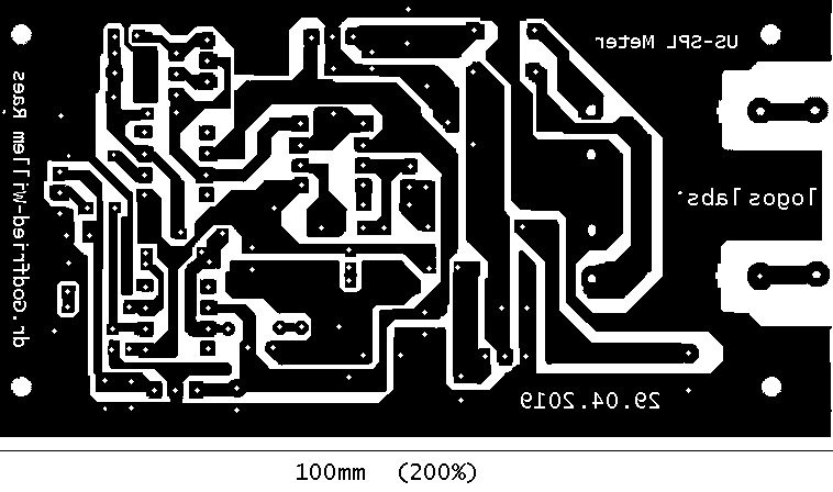 The
200% BMP drawing can be downloaded here.
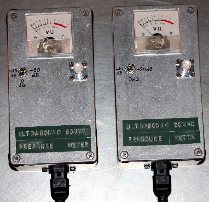
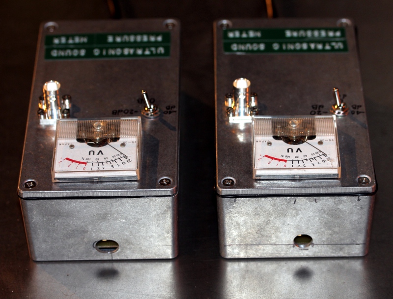
Here is a picture of two SPL meters, under construction:
The
200% BMP drawing can be downloaded here.
Here is a picture of two SPL meters, under construction:  Here is a screenshot taken from our oscilloscope, during measurement and callibration
of the meter:
Here is a screenshot taken from our oscilloscope, during measurement and callibration
of the meter: 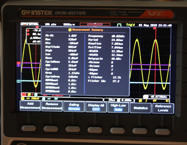 The bandwidth
of the meter in this version is 20kHz to 100kHz within 3dB. The sensitivity
is much better than in the first design. The BNC connector serves to connect
an oscilloscope, handy for monitoring the waveform as well as checking for clipping
if SPL level are very high. The MEMS microphone used can handle pressure levels
up to 124 dB. The RMS value of the signal at the BNC connector would then be
4.48 V. (12.6Vpp, for a sine wave). Higher levels can damage the microphone.
The measurement ranges are given in the following table:
The bandwidth
of the meter in this version is 20kHz to 100kHz within 3dB. The sensitivity
is much better than in the first design. The BNC connector serves to connect
an oscilloscope, handy for monitoring the waveform as well as checking for clipping
if SPL level are very high. The MEMS microphone used can handle pressure levels
up to 124 dB. The RMS value of the signal at the BNC connector would then be
4.48 V. (12.6Vpp, for a sine wave). Higher levels can damage the microphone.
The measurement ranges are given in the following table:
|
switch
|
VU meter reading
|
SPL at 30cm
|
SPL at 1m
|
|
0dB
|
-10dB
|
65dB
|
55dB
|
|
0dB
|
-3dB
|
72dB
|
62dB
|
|
0dB
|
0dB
|
75dB
|
65dB
|
|
0dB
|
+3dB
|
78dB
|
68dB
|
|
-20dB
|
-10dB
|
85dB
|
75dB
|
|
-20dB
|
-3dB
|
92dB
|
82dB
|
|
-20dB
|
0dB
|
95dB
|
85dB
|
|
-20dB
|
+3dB
|
98dB
|
88dB
|
|
-40dB
|
-10dB
|
105dB
|
95dB
|
|
-40dB
|
-3dB
|
112dB
|
102dB
|
|
-40dB
|
0dB
|
115dB
|
105dB
|
|
-40dB
|
+3dB
|
118dB
|
108dB
|
The reference level for SPL is 0dB = 20µPa. The standard distance for acoustic measurement is 1 m. It is common practice to use the distance at 30cm for ultrasonic measurement. The difference is exactly 10dB, as made clear in the table above.
A note on damping.
The damping of sound when passing through a medium such as air, increases as the frequency of the sound wave increases. Thus, if the -3dB value for a sound wave of given amplitude and frequency 20kHz equals 10 meters, this value becomes at 50kHz 3 meters and 2 meters at 100kHz. The velocity of sound, by the way, is also dependent on frequency!
D = 20 log L + hL
L is the distance to the sound source in meters. The value for h is 0.6dB/m at 20kHz, 2dB/m at 50kHz and 3dB/m at 100kHz.
D is the damping in dB. Note also that damping is typically a function of relative humidity of the air. As the humidity increases, the damping for higher frequencies increases as well!
All these factors taken into account, the job of designing a truthfull sound pressure meter for ultrasonics seems to become a cumbersome undertaking... Nevertheless, the meter as presented here is quite reliable and has been tested and verified with about ten different transducers. The precision is better than 3dB within the frequency range 20 kHz to 100 kHz. Here are some pictures:
Further possible impovements:
The precision of our instrument can still be improved by subsituting the AD736 true-rms convertor chip with an AD637, or even AD536. These laser trimmed chips however are very expensive. Here is a circuit drawing, using the AD637 chip:
 This chip, by
the way, can also be used as a logaritmic amplifier with a 60dB range.
This chip, by
the way, can also be used as a logaritmic amplifier with a 60dB range.
dr.Godfried-Willem Raes
Ghent, 30.09.2015, rev. 08.05.2019
Notes:
(1) This project is part of the ongoing research of the author in gesture controlled devices over the last 40 years. Systems, based on Sonar, Radar, infrared pyrodetection, accelerometers and other technologies are fully described in "Gesture controlled virtual musical instrument" (1999), in "Quadrada" (2003), "picradar" (2004) as well as in his doctoral dissertation 'An Invisible Instrument' (1993). Artistic productions and compositions using these interfaces and devices have been: <Standing Waves>, <Holosound>, <A Book of Moves>, <Virtual Jews Harp>, <Songbook>, <Slow Sham Rising>, <Gestrobo>, <Technofaustus> , "PicRadar Studies", <Namuda Studies> etc.
(2) Knowles Acoustics, datasheet for the SPH0642HT5H-1
(3) Analog Devices, datasheet for the AD736
(4) Analog Devices, datasheet for the OP27
(5) Our <Tinti> robot in particular made this instrument essential, as frequency modulated ultrasound is an intrinsic part of the design.
(6) Burr-Brown, datasheet for the OPA627 opamp.
Bibliographical references:
BHATIA, A.B. "Ultrasonic Absorbtion, an introduction to the theory of
sound absorbtion and dispersion in gases, liquids and solids", ed. Oxford
University Press, London, 1967
RAES, Godfried-Willem "Een onzichtbaar muziekinstrument" (Gent, 1993)
RAES, Godfried-Willem "Gesture controlled virtual musical instrument" (Ghent, 1999)
RAES, Godfried-Willem "Logos @ 50, het kloppend hart van de avant-gardemuziek in Vlaanderen", ed. Stichting Kunstboek, Oostkamp 2018.
SINCLAIR, Ian Robertson., "Sensors and Transducers" (London, 1992) , ISBN 0 7506 0415 8
First published on the web: 29.09.2015 by dr.Godfried-Willem Raes
Last update:2019-05-08