Solenoid General Application Guidelines
Open Frame Solenoids
Open frame solenoids are a basic, opened-coil type of linear motion solenoids. Due to their simple design structure, they are less costly, and are offered in a wide variety of sizes and types to best meet your application requirements.
Permanent Magnet (Self Holding) Solenoids
Self-holding solenoids generate a magnetic force ins tantly by applying a current to coil, and then maintaining the plunger in position without applying a current, via utilization of a permanent. The use of high performance permanent magnets and the improvement of the magnetic circuit provide highly efficient performance.
Tubular Solenoids
Tubular solenoids are tube shaped solenoids in which the coil portion is covered by a metal case. They are designed to obtain maximum force over a wide range of long or short strokes. two types of push and pull tubular solenoid are available to meet your application needs.
Small Push-Pull Solenoids
Small push-pull solenoids fulfill the need for miniaturizing, while maintaining output and cost efficiency. These small push-pull solenoids are suitable for space conscious, low-cost applications.
Push-Pull Solenoids
Push-pull solenoids have coil covered by a metal case with a flange as an auxiliary magnetic pole, so that even a small size solenoid can generate a large force. The standard pole configuration is conical type that is designed for medium stroke application. It is acceptable to modify pole configuration to be flat or other angles. Please consult to Sun magnet for further information.
Rotary
Rotary solenoids are designed to provide direct rotary motion. In order to convert the linear force of a push-pull solenoid into rotary motion, the case and armature are provided with specially designed spiral grooves, called "ball races". If you use a cam or a crank lever to convert a linear force into rotary motion, please consider using our rotary solenoids in your unit for a simpler, more reliable application.
Design a special solenoid or custom design to meet your specific needs
Sun magnet can design and manufacture solenoids according to customer's special requirements. The solenoids shown in this catalog are our standard model now to have a solenoid designed and developed according to your needs, please contact to us for further information.
The comparison between forge production and lathe process
.Speedy production
| The parts can be produced for 72pcs per minute base on forge production that is faster than normally lathe process above tens times. |
.Material loss
|
There is no material loss on forge production while the material loss on lathe process is depended on outline shaped. |
.Precision specification
|
The outline specification tolerance base on forge production is small and stable while the tolerance on lathe process is unstable. |
.High strength
| The forge technology can combine above two different kinds material and produced base on integrity parts that constitution strength is hundreds times better than normally lathe process that parts are combined after processes. |
.Meterial Variety
| Highly permeable magnetic coefficient material for forge production, it can use the material of highly permeable magnetic coefficient (The lower carbon percentage in material, the easier for forge production) but the material used in lathe process is limitation that has to easier for cutting. |
.Competitive cost
| The forge production cost is much lower than lathe process. |
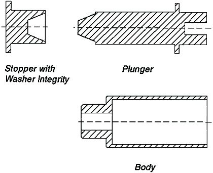
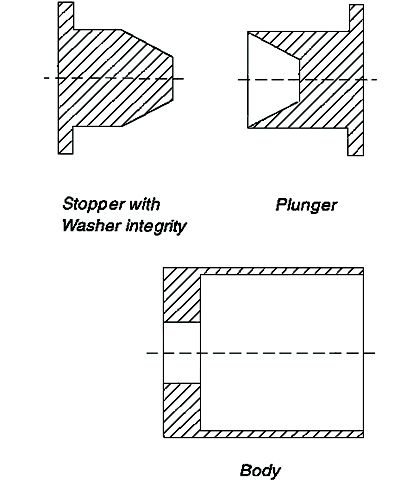
Available Forge Solenoid Parts
The solenoid parts that can be manufatured by forge machine includes stopper, plunger and solenoid body. The available forge parts and shape for each model are as follows.
.Open frame solenoid and permanent magnet(selfholding) solenoids

.Tubular Solenoid
.Push-Pull Solenoid & Rotary Solenoid
Current Forge Solenoid Parts Used in Sun Magent Model
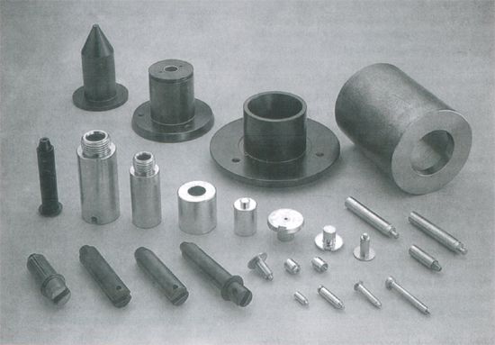
Above photo illustrates sun magnet's typical shape of forge parts. The current available diameter of forge parts are in Ø100mm. It is not always any kinds of shape those can be produced by forge integrity directly. However, it can be produced by forge integrity firstly to get roughly shape and then lathe secondary process to meet customer's specification required. It also can make cost down a lot through this way. It is base on rated quantity for forge production. If you have special requirements, please consult to Sun Magnet for further information.
Duty Cycle
Duty cycle is the term used to define the heating factors of a solenoid to prevent thermal damage. Duty cycle is normally expressed as a percentage and is defined as: the solenoids “on time” divided by the sum of the “on time” plus the “off time”:
| Duty Cycle(%)= | on time
on time + off time |
X 100% |
Duty cycle is important because a product of applying electrical power to the coil is heat. This excess heat can thermally damage the coil. Thus the term duty cycle is used to assure that only the safe maximum amount of electrical energy is applied to the solenoids. As an example, if a solenoid is rated at 7 watts continuous duty, this means that the solenoid coil can operate continuously (100% on time) with an input power lever of 7 watts with no thermal damage. The continuous duty rating is tested by lab. However, if increased energy output is required, then this can be accomplished by increased power input but it will cause temperature rised and lead to permanent thermal damage in the coil. To prevent this, the solenoid must be operated in an“on”and“off ”mode. Therefore if the input power level is increased to 14 watts ( double the continuous duty rating ) the solenoid's duty cycle must be dropped to 50% to prevent thermal damage. Additionally, the maximum“on ”time needs to be considered.
Maximum on Time
When a solenoid is actuated, current is applied to the coil. A product of this is temperature rise in the coil. When a solenoid is energized continuously, heating of the coil increases until a saturation level is reached which is equal to the ambient heat radiation. When a solenoid is operated in an intermittent (on-off) matter, the“on”time becomes critical if higher voltages ( thus currents ) are applied to the coil. These higher currents cause higher coil temperatures that can exceed the cooling capacity of the solenoid through ambient radiation. This heat rise can thermally destroy the solenoid's coil. To avoid such a catastrophic failure, there is a maximum“on”time, which is the longest time the solenoid can be energized without thermal damage. The maximum“on”time has been determined for each duty cycle, and is shown in the coil data.
Ampere Turn
Ampere turn describes the electro-motive force that causes a solenoid to actuate. Ampere tum is the product of the applied current to the coil, multiplied by the number of turns of magnet wire, as shown in the formula below:
| Ampere Turns= | Voltage
Coil resostamce |
X coil number turns |
Energy output of a solenoid is proportional to the number of ampere turns. The larger the number of ampere turns, the larger the mechanical energy output. However, the ampere turns should not below to 10% duty cycle, as all solenoids reach magnetic saturation at 10% level duty cycle, increasing ampere tums will not obviously increase energy output. If you have special requirements, please consult to Sun Magnet for further information.
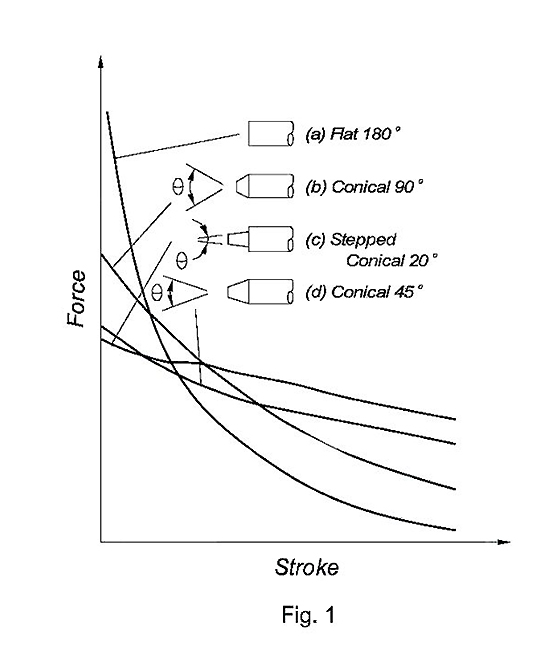
Plunger Configuration
the shape of the infernal end of the plunger influences the force-stroke characteristic of a given solenoid. This shape can be varied to meet specific requirements. In DC applications a conical shaped plunger is most commonly used. A comparison graph of four solenoids is equivalent in every way with the exception of the shape of the plunger. The flat plunger face will provide a large force through a short stroke while a conical shaped plunger will provide more force at longer stroke. For conical shaped plunger, the smaller plunger angle has, the larger starting force solenoid provides but holding force will be smaller. Please refer to Fig. 1 that illustrates the influence of various plunger shapes on the slope of the force-stroke curve.
Heat Sink
In order to reduce coil heating and to enable a larger ampere turn to be employed, a heat sink should be attached to a solenoid. Coil data of rotary solenoids, push-pull solenoids and tubular solenoids are measured and tested with a standard heat sink attached. Without a heat sink, a lower voltage than specified on the coil data charts, or lower duty cycle, must be used to avoid thermal damage to the coil. The coil data of small push-pull solenoids, self-holding solenoids and open frame solenoids, is shown without use of a heat sink.
Safety Factor
To reduce potential problems due to energy less through temperature rise in the coil and voltage fluctuation, a safety factor of 1.5 is recommended (required output *1.5). It is possible to use a smaller
safety factor, but precise application testing should be performed under all possible conditions.
Temperature Effects on Performance
Coil and performance data shown in this catalogue are measured at an ambient temperature of 20°C. When a voltage is applied to a coil, the coil temperature rises. This temperature increase causes an increase in the coil resistance. As a result, the energy output will decrease. The relationship between the coil temperature and the coil resistance has to be considered. To select the appropriate solenoid, it is necessary to consider the final temperature of the solenoid in your application. To determine the value of force or torque after coil temperature increase, the ampere turns after coil temperature rising must be calculated from ambient temperature base on the following formula:
| t= | R2 - R1
R1 |
X (234.5 + t1) + t1 - t2) |
t = temperature rise (deg. )
R1 = initial coil resistance (ohms)
R2 = final coil resistance (ohms )
t1 = initial ambient temperature(°C)
t2 = final ambient temperature(°C)
Response Time
The response time for solenoids is the time from when a voltage is applied to the coil until a given stroke has been achieved. The data in this catalogue Uses a coil temperature of 20°C as a reference point, without any load. Response time will become longer when a load is applied to the solenoid.
Arc Suppression
The solenoid coil is an inductive load that has a high inductance. As such, caution should be taken in the form of arc suppression when energizing and de-energizing the coil.
Power Supply
All of our standard solenoids are DC type. if the power supply available is AC, then a rectifier is required to convert AC to DC. The rectifier should be a full wave rectified type. Consult to Sum Magnet for recommendation.
How to Calculate Non-standard Duty cycle and Voltage
The voltage of a solenoid at a duty cycle not shown in the coil data, is determined by the following formula:
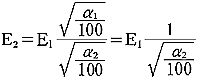
E1 = Voltage at 100%Duty cycle (VDC)
E2 = Voltage at α2 (VDC)
α1 = 100% duty cycle
α2 = duty cycle to be used
Electrolytic Corrosion of Coil
When the solenoid is used in an environment of high temperature and high humidity, and the case is ground, the coil may corrode and fail under electrolytic action. To eliminate this potential problem, the following precautions should be observed.
1.Ground the positive (+) lead of the power source.
2.When circumstances preclude the grounding of the positive (+) lead of the power supply, or require the grounding of the negative (-) lead of the power supply, install a switch in the positive (+) lead of the power supply and connect the negative (-)lead to the coil.
Use of Characteristics table
Tables are provided for each size of push-pull solenoids, tubular solenoids, open frame solenoids, and self-holding solenoids, which show stroke vs. force curves at four duty cycles (100%, 50%, 25%, and 10%). For rotary solenoids, the table shows every size's duty cycle vs. torque curve for each rotation angle. Decide the size of the solenoid needed in your application, then move to the page for that size, and review detail of the solenoid.
Conversion of Units
1 N ( Newton) = 0.102 (kgf) =102 (gf)
1 kgf = 9.807 (N)
1 Nm = 10.197 (kgf cm)
1 MPa = 10.197 (kgf / cm2)
1 kgf / cm2 = 0.098 (MPa)
1 inch = 25.4mm
1ºC = 5/9 ( ºF -32)
1 ounce = 28.35 g
1 N = 3.6 ounces
1 Pound = 16 ounces
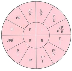
Ohms Law and Power
l = ampere
R = ohms
E = volts