Dr.Godfried-Willem RAES
Kursus Experimentele Muziek: Boekdeel 2: Live electronics
Hogeschool Gent : Departement Muziek & Drama
| <Terug naar inhoudstafel kursus> | MOTORS | Dit hoofdstukje is niet beschikbaar in het nederlands. |
2114:
Application
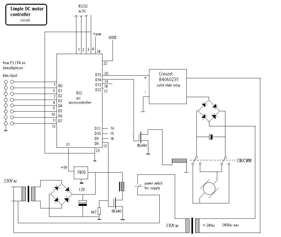
<Controlling the speed of large DC motors>
The speed of a DC collector motor (brush motor) is a function of applied voltage. Torque is a function of the current of the motor, so it is not possible to lower the speed without lowering the torque. Larger motors require pretty high currents, which are difficult to control using current or voltage regulating circuitry. PWM is the standard answer to the problems, but has its own tricky sides: if the modulated wave is too low (below audio) in frequency, the motor will become a hefty soundsource and therefore make musical applications (automated instruments) nearly impossible. At the other side, if you take the frequency far above audio, the heat developped in the power Mosfet's may tend to become prohibitive. Also -an important consideration for our own performances using sonar versions of my invisible instrument- there will be a lot of ultrasonic noise making sonar impossible.
So, we came up with a completely different approach: instead of regulating a DC power supply using a series transistor, IGTB or mosfet, we designed a simple circuit that regulates the AC supply using solid state zero-cross triac of thyristor modules. We used Crouzet solid state relays with a control switch input range of 3 to 32Volts DC and an output switch capacity up to 10A at a minimum AC voltage of 24V.
The Basic Stamp, a PIC microcontroller, reads a byte from the input port and converts this in a periodic pulse on output pin 20. The minimum ON-time should be 10ms (for a 50Hz mains supply) and the on/off time of this signal will determine the average voltage seen by the motor. The solid state relais switches only on zero crosses of the AC voltage. At 50Hz, there are 100 such crosses a second. So, if we let pass only 1 half wave a second, the output voltage will be 1% of the maximum value. If the motor has a very low mass, you should use a very large smoothing capacitor over the motor. If the motor has a high mass or drives some kind of flywheel (for instance a large fan), than the capacitor value can be taken very low.
It obviously helps for smooth operation of the motor, to spread ON/OFF pulses evenly over the period used. So, for 25% power, following pattern should be used:
1000100010001000100010001000100010001000 ....
For 50%:
1100110011001100110011001100110011001100..., each bit corresponding to a duration of 10ms.
Output pin 19 controls a relais, used to control the direction of rotation of the motor (CW/ CWW). Pin 13 is shown connected to another relais wherewith the complete power circuit for the motor can be switched on or off.
Both the solid state relais and the bridge rectifier should mounted on a large heatsink.
last update: 2015-04-26
| Terug naar inhoudstafel kursus: <Index Kursus> | Naar homepage dr.Godfried-Willem RAES | Deze pagina is niet beschikbaar in het nederlands |