dr.Godfried-Willem RAES
Kursus Experimentele Muziek: Boekdeel 2: Live Electronics & Robotics
Hogeschool Gent : Departement Muziek & Drama
| This page is only available in English | BUILDING PROJECT |
A simple pulse generator for measurements on solenoids for robotics and automated musical instruments
Striking objects such as strings with felt covered hammers in pianos, mallets on vibraphone staves, sticks on drums etc... can be automated using solenoids or electromagnets of two different kinds:
For both types, the striking force can be controlled either by varying the voltage applied to the coil (1) or by controlling the duration of a pulse with fixed voltage. In the first case we would control the height of the pulse, in the latter the width. Technically it is a lot easier to vary the pulse with of a signal than to control its voltage. Pulse width control involves a timing circuit and a switch whereas voltage control requires a power amplifier.
In fact it is the total energy fed into the solenoid that will determine the striking force of the device. This is proportional to the surface size of the pulse applied. Once we decide to go for pulse width control, we still have to decide on a particular voltage to use. The higher we take this voltage, the shorter our pulses can be for a same stroke. Practically, in this kind of applications one should not exceed the nominal 100% duty cycle voltage specified by the coils manufacturer by more than a factor five. (Thus operating a 12V solenoid on a pulsed regime of max. 60V pulses).
For any automated instrument or robot we design, one needs to perform measurements with the solenoids in order to find out the useful range. Hence we designed following simple and very cheap circuit to perform these tests.
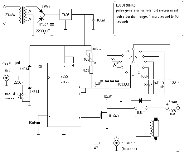
The trigger input gets its signal from a low frequency pulse oscillator (set to 1Hz to 5Hz). You can also cause a single pulse by pushing the button. (Note that we did not provide a debounce circuit, for simplicity). The frequency of the trigger signal should obviously be lower then the period set for the pulse. Otherwise the monoflop will retrigger and consequently the output will be high all the time. The trigger input circuit includes a capacitor functioning as a differentiator and limiting the trigger pulse to ca. 4µs. This way the circuit can also be triggered with AC signals. The test voltage for the solenoid is applied over the indicated contacts. We strongly advise the use of a bench lab power supply (0-60Volts, 0-6A) with readings for voltage and current as well as a current limiting control. The multiturn 10k potmeter (Bourns) allows us to set the pulse length with great precision. When the 1 µF cap is selected with the 12-position rotary switch, the range of the pulse duration can be set between 900 µs (microseconds) and 11ms (millisecond). With each change of capacitor, we shift the range a decade up or down. We can read the values from an oscilloscope connected to the pulse output. Digital scopes (Fluke) are particularly suitable to this end, since they allow precise pulse measurements to be made. It is advisable to use low leakage MKM capacitors for the ranges requiring stability and precision (10µF, 1 µF, 100nF) and styroflex for the lower values. (2)
Limiting factors in any design using pulsed solenoids are:
- if we go for a lower voltage we need longer pulses. However this compromises the highest possible repetition rate we can produce with our solenoid. If you want your automaton to be capable of playing say 16 notes (strokes) a second, the the maximum pulse width that can be applied will be: (1/16) / 2 = 31ms. The divide by two should be observed: first off all, this time covers the time required for the solenoid to fall back (either through gravity or through the action of a spring); in the second place, because this limits the duty cycle to below 50%.
- if we go for higher voltages, we have to be careful not to exceed the power handling capacity of the solenoid when high repetition rates are in effect. The most important limiting factors for repetition rate are: magnetic hysteresis of the core, heat dissipation limits in the coil windings, mechanical friction and resonance's in the moving parts.
- maximum striking force depends on the magnetic saturation of the anchor. It makes no sense to apply more energy to the coil than that amount that saturates it. It is easy to find this out: saturation occurs when further lengthening of a pulse does no longer lead to an audibly stronger stroke.
Our experience with many different kinds and brands of solenoids and automated instruments led us to always aim at pulse width control ranges between 250 microseconds and 25ms. A decade of control (say 1-10ms), within these margins, is generally more than what you could get out of your coil.
Notes:
(1) In fact it is also possible and even very easy to use pulse width modulation to vary the effective height of the pulse and thus the average voltage. However, it should be strongly discouraged to do this in any component of automated musical instruments: generally PWM causes audible noises from the solenoids. If you think you found a solution by using a well above audio frequency at the other hand, you will quickly discover problems with heat build up in the Mosfets (requiring heatsinks and even blowers...) as well as in the solenoids, since these will dissipate all the high frequency components as heat. In top of this, you will create a cause of very strong electromagnetic broadspectrum noise making many audio technologies problematic in the same environment.
(2) The 10pF cap in the schematic is not functional, unless you find a (7)555 chip capable of producing nanosecond pulses. For ordinary parts the limit is between 100ns and 800ns. If a pulse generator for very short pulses in the nanosecond range is required -bit this will never be the case in the context of solenoid driving circuitry- you should select a TTL monoflop chip (74HCT121 or 74HCT221) instead of the 555.
Final remark:
experimentally oriented musicians may discover that this circuit can be used as a very nice frequency divider and filter in analog sound generation in the studio or on stage: try feeding the trigger input with a signal faster then the pulse length set on the device, play around with the knobs and listen to what happens. You might be surprised. (In these experiments, you may also omit the 220pF on the trigger input. If you want to modulate the effects, you can apply a modulation signal to pin 5, after removing the 10nF cap to ground there).
Filedate:15.09.2003 - Last update: 2003-09-16
|
Terug naar inhoudstafel kursus: <Index Kursus> |
Naar homepage dr.Godfried-Willem RAES |