|
Musical Robot |
|
<Bono>
an automated rotary valve trombone Godfried-Willem RAES 2005-2007 |
|
Musical Robot |
|
<Bono>
an automated rotary valve trombone Godfried-Willem RAES 2005-2007 |
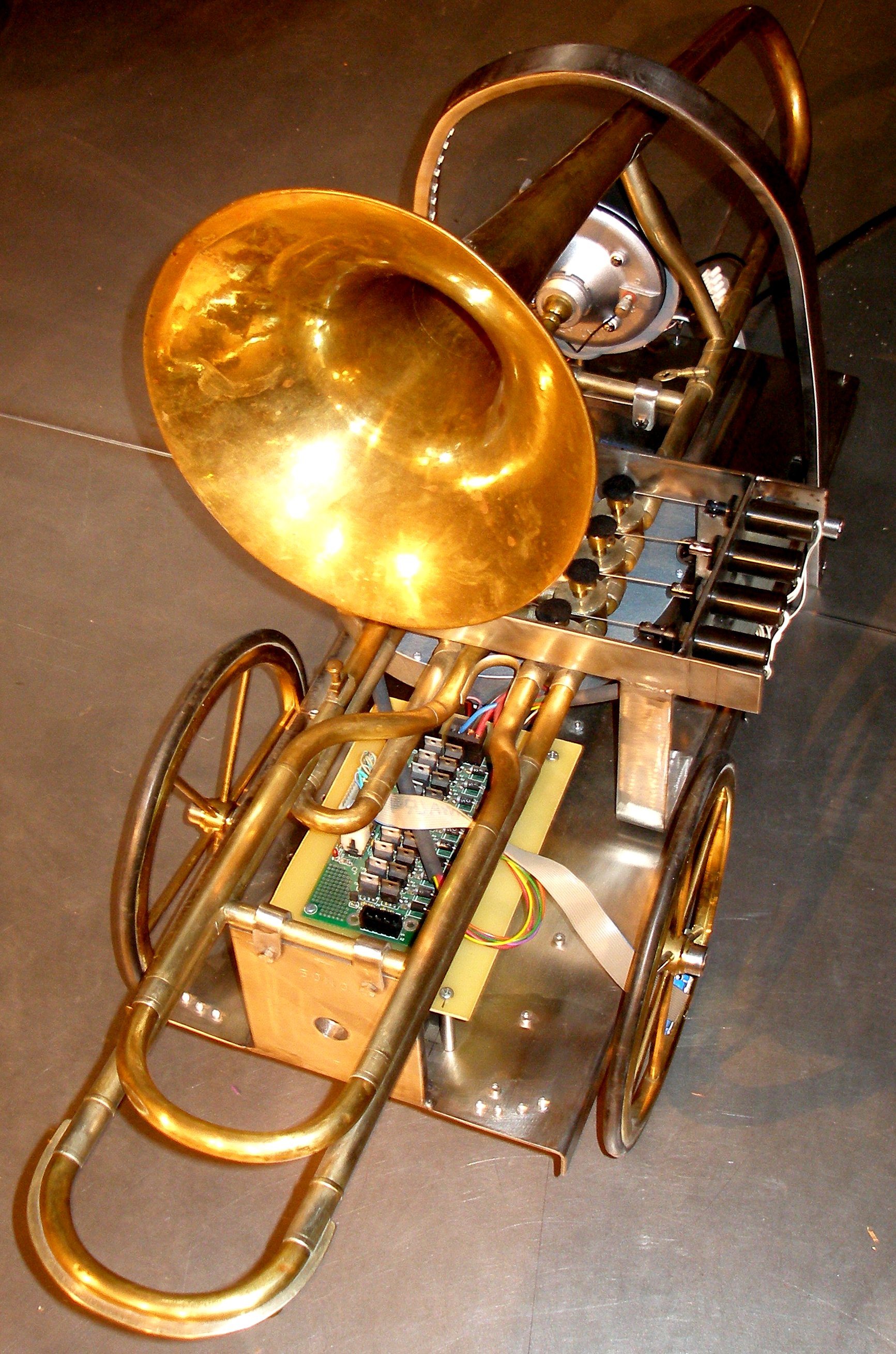
Robot: <Bono>
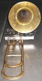
This musical robot consists of an old but extremely well made valve trombone,
found on the Ghent flea market. It was build by the famous brass instrument
builders V.F.Cerveny and Sons in Hradec Kralove (Tchechia) 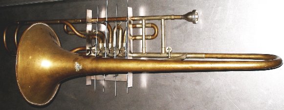 We
equipped it with an automated playing head and four automated valves. Wind supply
-we use a small rotating compressor- is also automated. Controlling this robot
is realized using a standard midi protocol. This instrument has four rotary
valves. Normally these valves rotate over a 90 degree angle under finger operation.
The drawing illustrates the internal workings of this type of valve:
We
equipped it with an automated playing head and four automated valves. Wind supply
-we use a small rotating compressor- is also automated. Controlling this robot
is realized using a standard midi protocol. This instrument has four rotary
valves. Normally these valves rotate over a 90 degree angle under finger operation.
The drawing illustrates the internal workings of this type of valve:  When
we started the automation of this mechanism we had many technical choices with
regard to the way the valves could be operated:
When
we started the automation of this mechanism we had many technical choices with
regard to the way the valves could be operated:
1. The most trivial solution seemed to be to preserve the existing mechanism and replace the human fingers with push type solenoids pushing on the existing fingerplates. The problem with this approach is that operation of the valves is very sluggish, mainly because the return spring now also has to lift up the anchor of the solenoid. A second problem is that due to the many mechanical parts, the action tends to be rather noisy. For these reason we abandoned this track.
2. A second possibility consists of activating the axis of the valves directly using angular displacement solenoids. The problem here is that angular displacement solenoids operating over full 90 degrees angles are difficult to find, 45 degrees being the most common standard. Also, the 90 degree types are pretty noisy whenever they reach their end positions. One could of course go with a design using two 45 degree rotary solenoids for each valve, each operating on another side of the axis. At rest all valves would then be in a halfway depressed state. In this case we would need eight solenoids.
3. A third possibility was to use motors (stepper or servo) to rotate the valves on their axis in steps of 90 degrees. The advantage of this last approach being the unsurpassed speed that can be achieved from the valves, however at the detriment of complexity: position sensors become a mandatory requirement. With stepper motors, small types doing 7.5 degrees per step could be used. These require 12 steps for a 90 degree angle and are pretty silent in operation. However their torque is marginal if they have to rotate worn out or not to well greased valves.
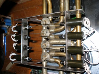
4. A fourth possibility consist of using eight pull-type tubular solenoids working on the eccentric pivot point on the valve shafts. Here we get rid of the entire original mechanism and replace it with traction wires made of 1.6 mm stainless steel rods.
During the research phase we tried out the third and the fourth possibility.
We rejected the third mainly because the acceleration of the steppers could
never be made fast enough for a good and lively response of the keys. The fourth
possibility was realized using Black Knight pull type solenoids. In order to
get fast response we drive them using our pulse/hold PIC controller boards as
developed for our <player piano> , for <Bako> and for <Qt>.
The force they are able to develop is only marginal for smooth operation in
this robot. The circuit principle is shown in the schematic below:
In total, three PIC-microcontroller boards are used in this robot: A first one placed on the midi-input and hub board, controlling the motor functions, the expression valve and the visual effects. A second one takes care of the valve combinations used for resonance on the required notes. A third one, -equipped with a dsPIC, type 30F3010, controlling the artificial mouth assembly and the pitch generation. This board also has two digit decimal displays, showing the midi note playing. We used a TIL311 display, because this type has an on chip BCD to 7-segment decoder. When no note is playing, the display will read 'FF'. (Not zero, because 0 is a valid midi note!).
For the construction of the artificial mouth we could build further on the experience gained when realizing our automated sousaphone, <So>. However, we also tried out a few other sound generating mechanisms prior to taking up the <So> design again. Thus we tried a servo motor driven rotary valve working on compressed air. This worked soundwise excellently - we could obtain really impressive fortissimos for instance over the entire compass. We finally rejected the application of this technology because we were unable to control the servo fast enough in going from the one speed to the other as required for proper generation of musical pitches. The second problem had to with the difficulty in finding really silent compressors.
The overview of the total circuitry looks like:
The <Bono> robot was designed to be suspended, thus reducing floor space requirements for the <M&M> robot orchestra. All mechanical parts were made from stainless steel, welded together using the manual TIG process. All serviceable parts can be taken apart however.
Power supply voltages and currents:
Midi Mapping and implementation:
Midi note range: [0-33] 34 - 63 [64-72]. Note on with velocity is implemented
and has a wide control range. For a good attack, low values for velo and a high
setting for controller 17 should be used. (see further in this implementation
tabel).
Note Off commands are required, but can be dropped for pure legato playing. Note-off stops the mouthpiece driver and de-energizes the valve solenoids.
Lights:
Controller 1: [version 1 & 2 to only] wind pressure (motor speed), Note that this is not a volume control, but the wind pressure greatly affects the realism of the produced trombone sound. Users should set this controller to the highest possible value wherewith a good sound is produced. Soft sounds require less wind. Note that the wind also serves as a cooling mechanism for the mouthpiece driver. Therefore it is illegal to play notes without supplying wind.
Controller 7: General volume control. There is a build in integrator, such that very fast changes for this controller are averaged out. Integration time is in the order of 15ms. This is the controller to use for crescendo and descrescendo playing. It also can be used as an excellent tremolo controller as well as for advanced enveloppe control.
Controller 17 is used for the attack level and thus contributes to the volume scaling. Note that this setting affects greatly the effect of the velocity byte as well as that off the attack-time controller (controller nr.18). The intrinsic relation is shown in the graph below:
Controller 13 changes the lookup table for the valve-pitch correspondence
| Value | -1/2t | -1t | -1 1/2t | -2 1/2t | remarks |
| 0 | default empirical [detailed mapping] (txt.file) | ||||
| 1 | acoustic [detailed mapping] | ||||
| 2 | user table 1 (sysex programmable) | ||||
| 3 | user table 2 (sysex programmable) | ||||
| 4 | off | off | off | off | 4-7 valid |
| 12 | on | off | off | off | 12-15 valid |
| 20 | off | on | off | off | 20-23 valid |
| 28 | on | on | off | off | 28-31 valid |
| 36 | off | off | on | off | 36-39 valid |
| 44 | on | off | on | off | 44-47 valid |
| 52 | off | on | on | off | 53-56 valid |
| 60 | on | on | on | off | 60-63 valid |
| 68 | off | off | off | on | |
| 76 | on | off | off | on | |
| 84 | off | on | off | on | |
| 92 | on | on | off | on | |
| 100 | off | off | on | on | |
| 108 | on | off | on | on | |
| 116 | off | on | on | on | |
| 124 | on | on | on | on | |
| other | invalid |
Controller 18: attack time (see graph under controller 17). This sets the time the volume will remain at the level set by controller 17, before falling back to the value set with the velocity byte.
Controller 20: tuning (diapason, default is 440Hz). The range is limited to maximum 50 cents (a quartertone) upwards.
Controller 21: second partial amount (for expert use only)
Controller 22: Third partial amount (for expert use only)
Controller 25: Valve solenoid pulse duration (for research and development only)
Controller 66: Machine power on/off switch (mandatory). As long as controller 66 is not set to on (any non-zero value), <Bono> will not play anything.
Controller 123 switches all notes off. Releases the solenoid valves. Resets the controllers, except nr.20. Also switches off the lights.
Program change: implemented. Program changes are used to let 'quick and dirty' users set presets for certain limited musical applications. It saves them the burden to get into the interpretation level of music, at the detriment of nuance. The implementation and program numbering scheme will we analogous to the ones developed for <So>.
Pitch bend implemented. The range is limited to +/- a semitone. Pitch bend can be used for microtonal music as well as for vibrato control.
Technical specifications:
Design and construction: dr.Godfried-Willem Raes
Collaborators on the construction of this robot:
Music composed for <Bono>:
| Back to composers guide to the M&M robot orchestra. | Back to Main Logos page:index.html | To Godfried-Willem Raes personal homepage... | To Instrument catalogue |  |
Robot: <Bono>
In het M&M robot orkest hadden we behoefte aan wat meer variatie in de lage blaasinstrumenten, in dit tessituurgebied domineerden immers alleen <So> en de toch wat minder responsieve <Bako>. Voor deze automatische ventieltrombone gebruikten we bij onze eerste experimenten -waarbij we zochten naar een alternatief voor het mechanisme dat we ontwikkelden voor <So>- een persluchtmotor met drie schoepen als klankopwekkingsmechanisme. Deze persluchtmotor -hier gebruikt als kompressor - werd daarbij aangedreven door een uiterst nauwkeurige servo motor. De korrektheid van de intonatie staat of valt immers met de precizie van deze motor en zijn aansturing. Zouden we een dergelijk systeem zonder meer toepassen, dan zou de luidheid van de voortgebrachte tonen een funktie zijn van de toonhoogte. Dit is muzikaal uiteraard niet erg wenselijk. Daarom is ook een regeling van de windinlaat van de kompressor hier een absolute vereiste. Het mechanisme werkte naar toonkwaliteit erg goed en was in staat impressionante fortissimos te genereren, maar leed aan een niet te vermijden traagheid bij het snel wisselen van tonen. Een na enige tijd onuitstaanbaar portamento bleef een inherente eigenschap van het koncept. Daarom pasten we in de tweede versie opnieuw een moving coil driver toe, een in een aantal opzichten verbeterde versie van die toegepast in <So>. De rezultaten in de hoogte van de tessituur bleven echter onbevredigend, zodat we in versie drie -de meest recente- overstapten naar het gebruik van een akoestische impedantietransformator gekoppeld aan een 100W kompressiedriver. Hierdoor werd het oorspronkelijk ontwikkelde windmechanisme overbodig. Van meet af aan bouwden we <Bono> zo, dat het instrument ook probleemloos overweg kan met kwarttoonsmuziek en muziek in andere stemmingen in het algemeen.
De ventielen op deze bijzonder goed gebouwde trombone zijn draaiventielen. De Boheemse oorsprong van het instrument, gebouwd door V.F.Cerveny in Hradec Kralove in het huidige Tchechie, is daar uiteraard niet vreemd aan. Daardoor kon echter niet hetzelfde mechanisme worden toegepasten als bij <So>, die met drie duwventielen is uitgerust. Deze ventielen moeten immers over een hoek van 90 graden verdraaid worden om het ventiel te schakelen. In de ontwerpfaze onderzochten we grondig de verschillende mogelijkheden:
1.- Toepassing van duwmagneten op de bestaande hefbomen voor de vingers. Deze triviale mogelijkheid dienden we te verwerpen vanwege de te grote traagheid: de terugslagveren moeten nu immers ook het gewicht van de magneetkern omhoogduwen. Bovendien leidde de overmaat aan hefboompjes en draaipunten tot veel bijgeluiden, wrijvingsverliezen, traagheid en onbetrouwbaarheid.
2.- Toepassing van draai-elektromagneten. Deze hebben echter standaard een hoekverdraaiing beperkt tot 45 graden. Negentig graden types zijn zeldzaam en extreem duur. Bovendien zijn ze lawaaierig bij het bereiken van hun eindpositie.
3.- Toepassing van stappenmotoren. Hiermee kunnen de ventielen telkens over een hoek van 90 graden worden verdraaid. Maar, door torsie en wrijving bestaan de mogelijkheid dat de motoren op gezette tijden een of meer stappen missen waardoor de afregeling verloren gaat. Om dit te kompenseren zijn dan weer positiebepalingssensoren nodig. We hebben een proefprojektje opgezet met stappenmotoren met een stapgrootte van 7.5 graden, maar de versnellings mogelijkheden van deze motoren bleek te klein om erg soepel met de ventielen te kunnen omgaan.
4.- Toepassing van dubbele trek of duw magneten aangrijpend in het excenter punt van de oorspronkelijke vertielen, waarbij dan het gehele originele hefboommechanisme wordt verwijderd. Hiervoor pasten we Black Knight trekmagneten toe, voorzien van uit inox staaf geplooide trakturen. om die te plooien ontwikkelden we een speciale plooimal. De trakturen dienen immers onderling identisch te zijn. De lineaire verplaatsing wordt nu 10mm voor een draaihoek van 45 graden.
Deze robot maakt voor zijn interne besturing gebruik van drie mikroprocessoren: twee 18F2525 PIC's en een 30F3010 dsPIC. Gedetailleerde schakelschemas zijn aan het einde van deze pagina toegevoegd. Om het nodige podiumoppervlak voor het <M&M> robotorkest niet nog verder te vergroten, besloten we deze automaat te bouwen voor ophanging, hoewel opstelling op de bodem ook mogelijk is.
Godfried-Willem Raes
Pictures taken during the building of the <Bono> robot:

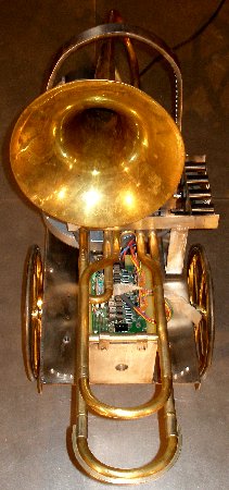
Construction Diary:
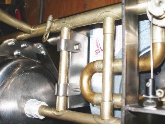
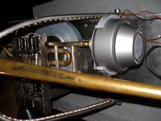
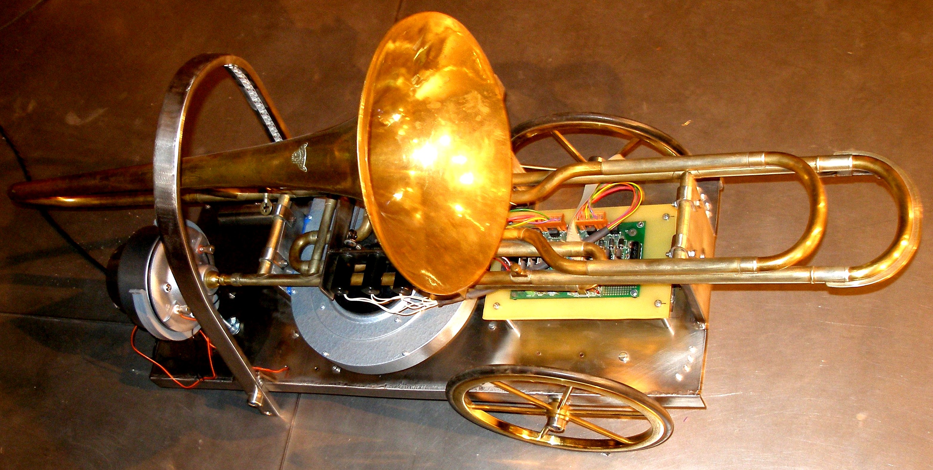
 Air inlet to the mouth and air outlet from the compressor can be seen on the
picture. Drilling of all mounting holes for the electronic circuitry. Drilling
of 12mm holes on the sides for either large wheels or suspension hooks. Moving
coil driver prepared and mounted in the mouth cavity container. Research on
pad material for the lip subtitute. Saxophone leather pads might be to soft
for a good sound in the trebble.
Air inlet to the mouth and air outlet from the compressor can be seen on the
picture. Drilling of all mounting holes for the electronic circuitry. Drilling
of 12mm holes on the sides for either large wheels or suspension hooks. Moving
coil driver prepared and mounted in the mouth cavity container. Research on
pad material for the lip subtitute. Saxophone leather pads might be to soft
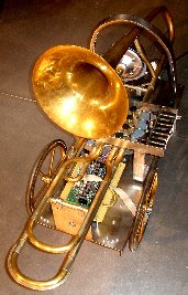
for a good sound in the trebble. It looks like we will need to design some kind of protective structure around
the backside of the robot, such that it can be placed on a surface without
risk of damaging essential components.
It looks like we will need to design some kind of protective structure around
the backside of the robot, such that it can be placed on a surface without
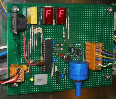
risk of damaging essential components.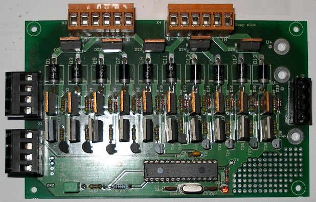 This
is the same board as we have used for our <Harma> robot (Board version
1.0). Wiring finalized. Connector X3 steers the pull-off solenoids, connector
X4 the pull-on solenoids. Wire color coding is: red=positive power supply
voltage, orange= left solenoid/valve, yellow= second left, green= second right,
purple= right solenoid/valve. Two outputs remain as yet unused.
This
is the same board as we have used for our <Harma> robot (Board version
1.0). Wiring finalized. Connector X3 steers the pull-off solenoids, connector
X4 the pull-on solenoids. Wire color coding is: red=positive power supply
voltage, orange= left solenoid/valve, yellow= second left, green= second right,
purple= right solenoid/valve. Two outputs remain as yet unused.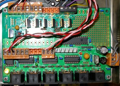
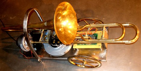
 The audio transformer used is a pre-world war two type taken from old professional
audio equipment with vacuum tubes. It measured out perfectly o.k. for our
application here.
The audio transformer used is a pre-world war two type taken from old professional
audio equipment with vacuum tubes. It measured out perfectly o.k. for our
application here.| (Terug) naar logos-projekten: | Terug naar Logos' index-pagina: | Naar Godfried-Willem Raes personal homepage... | Naar katalogus instrumenten | |
Last update: 2008-11-07 by Godfried-Willem Raes
Technical drawings and data sheets:
Midi input board and PIC controller:
Midi buffers and thru ports:
Microprocessor section (motor control & lights):


Solenoids used for the valve mechanism:
Black Knight 121 420 610 620, 12V nominal @100% duty cycle, Rdc=20.4 Ohm. diameter 20mm (25 Euro a piece, in 2006) Farnell order code: 4207439 . Positive hold voltage: 9V, negative pulse voltage: -17V. Force for a displacement of 15mm, at 12V: 0.49N (50gf), for a 1mm displacement at 12V: 7.84N (800 gf). Maximum allowable voltage: 160V
Moving coil driver:
ITT PB128 65.13-1-370-998 49101 10545 W.Germany, 8 Ohm, 20W. (modified: perforated cone and silicon mounted saxophone leather pad). Amplifier: ILP HY2001 module. Power supply transformer: ILP type 1UR18, toroidal, 230V ac @ 2 x 18V , 0.83A. Power: 30VA.
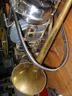
Trombone:
Vaclav Franticek Cerveny & Sons, Hradec Kralove (Tchechia). Probably from ca. 1928 or earlier. The factory closed in 1945. Equiped with 4 rotary valves. (1/2t, 1t, 1 1/2t, 2 1/2t).
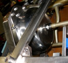
Mouthpiece connection to artificial head (Version 2.0):
Cable gland, Lapp Cable, Skintop MSR. Manufacturer type number: 52015810 PG16, clamping range 6-13mm. Farnell order code:117-8964. Locknut: PG16, 52003530 order code:117-8923. This piece has to be adapted in order to fit bono: mount the male-male thread piece the other way round so that the longest thread sticks into the stainless steel pot. This driver was replaced on 30.10.2008 with a motor compressor driver coupled to an acoustic impedance converter turned on the lathe from a real trombone mouthpiece. This is now version 3.0.
Potmeter on the DS-PIC board:
This multiturn potentiometer is used to adjust the maximum output level such that no harm can occur to the moving coil assemby or the compression driver. The setting should not be changed by users. Only qualified technicians should be allowed to interfere with this adjustment. The potmeter (the large blue component on the DS-PIC board) is a Bourns high quality wirewound potmeter with value 5k and forms the input attenuator for the HY2001 amp module. The input voltage to this module should not exceed 500mVrms.
Audio transformer:
This is a 1:1 audio transformer with impedance 600 Ohms. Brand: Oxford Electrical Products Ltd. Rdc is 109 Ohms : 134 Ohms. Frequency response: 30Hz - 25kHz. Power: 2mW. Farnell order nr.:117-2421. The theoretical maximum power, for a secondary voltage of 10V with a load of 4k7 is 21mW. Largely more than the specs. This will cause THD distortion at high levels. This is not a mistake but intended in the design. The original Rola transformer (version 2.0, out of use since 30.10.2008) was left in place but has no function any more. We are now at version 3.0. Note the single BA220 diode over one of the primary windings as well as the 150nF cap over the secondary: these components are essential for obtaining a trombone like sound from the instrument. The cap forms a formant filter (resonator) and the diode creates an asymetrical and non-linear (amplitude dependent) waveform. These component values were not calculated but found after many hours of experimenting with different arrangements and component values.
LED spotlite specs:
Programming information and settings for the Siemens Sinamics G110 motor controller:
| Parameter nr. | setting | comment |
| P0003 - User Access level | 3 |
|
| P0004 - access control filter params | 0 | allow access to all parameters of P0003 = 3 |
| P0005 - display parameter | 21 | display motor frequency |
| P0010 - commisioning params | 0 |
must be set to 1 to change motor params. For access to P4 params and normal operation, must be set to 0 |
| P0100 - Europe/ US | 0 | = default value (Europe, 50Hz) |
| P0210 - voltage | 230V | mains voltage |
| P0304 - nominal motor voltage | 132V | motor specs. |
| P0305 - motor current | 0.56A | motor specs. |
| P0307 - motor power | 0.07 kW | motor specs. |
| P0310 - nominal motor frequency | 50Hz | motor specs. |
| P0311 - nominal motor rpm | 2800 | motor specs. |
| P0700 - ctrl. via control panel or digital I/O | 2 | use digital inputs for ctrl. |
| P1000 - select frequency setpoint | 2 | set analog setpoint (1= operator panel f-ctrl) |
| P1080 - min.. motor frequency | 10 Hz | a minimum windflow is essential for cooling. |
| P1082 - max. motor frequency | 80Hz | the practical maximum freq. will be ca. 65Hz |
| P1120 - ramp up-time | 2" | |
| P1121 - ramp down time | 5" | |
| P2000 - max.frequency setpoint | 85Hz | controls the range mapping for the analog input |
| P3900 - end quick commisioning | 1 | resets P0010 |
Wiring motor controller connections (Version 1.0 and 2.0):

Technical ASCII description files for PIC-specs and lookups:
High resolution (300dpi) pictures of <Bono> for download: