<Radar 2017>
microwave radar based gesture controllers for embedded composition in robotic instruments
by
dr.Godfried-Willem Raes
post-doctoral
researcher
Ghent University & Logos Foundation
2017
Radar_2017 is a microwave radar based sensing system for capturing information on human body movement to be used for embodiment research, controlling automated musical instruments and robots with embedded interactive composition code. Of course the equipment could also be used as a stand alone controller for midi devices such as synthesizers or audio effect processors, as well as for real time audio processing. In these functions it contitutes an up-to-date alternative for our earlier sonar and radar based invisible instruments. With these sensor systems, it is possible to retrieve information about the speed of movement as well as the movement quantity of a body. The system is inherently wireless. These sensors are a further development of the two radar sensors we build and developped for our <Rodo> robot, turning it into a fully interactive audio art installation.
This technical paper presents the hardware, comments on its design, the software implementation as well as it discusses some artistic applications. The equipment is available at the Logos Foundation in Ghent (2). It is open to composers, performers and scientists for experiment and development of productions.
Hardware
In the Logos lab a very wide range of different radar devices have been and are further being researched operating in different frequency bands: 1.2GHz, 2.45Ghz (our Quadrada System), 9.35GHz (our PicRadar system), 10.58GHz, 12GHz, 24GHz (our Tetrada system), 77GHz and 5.86GHz (Bumblebee project).
This report reflects our findings and realisations using a board-based
doppler radar device operating in the 10.587GHz band produced by Microwave Solutions
Ltd. Here is the datasheet
for these devices.
The hardware side of these two prototype radar sensors consists of the following
electronic components.
1. Radar 3:
The signal from the microwave sensor is first amplified and filtered in the two opamps. The output is fed to the AN0 pin on the microprocessor. This ADC channel is configured to work in 12-bit resolution mode. The analog signal is also presented to a Schmitt trigger comparator circuit (CMP02) such that clean zero crosses of the input signal are created. These pulses are connected to the RP39 pin on the microprocessor, configured as an external interrupt input. The interrupt handler performs period measurement to obtain data for the speed of detected movement. PWM3 output channel of the microprocessor is used to generate a signal allowing either frequency adjustment of the microwave carrier or frequency modulation of the same. The idea here was to frequency modulate the carrier such that by comparing the phase of the modulator with its reflection , we could obtain absolute data on the distance of the detected moving body. However, in practice we didn't succeed in making this work reliably enough. Thus we dropped that part in the final design.
The circuits have a MIDI input serving a double use: first of all, it allows parameters for the embedded composition code as well as for the data acquisition to be changed on the fly. Secondly, all MIDI input data can be filtered and passed to the MIDI output such that it is effectively merged with the data stream generated by the interface itself. As a consequence, the sensors can be operated in a pure transparant mode on our musical robots. The MIDI output and THRU signals are pure differential using a 75174 chip, such that very long cables can be used without sacrificing compatibility with standard MIDI devices.
The single sided hand-drawn PCB for this circuit (200%) is:
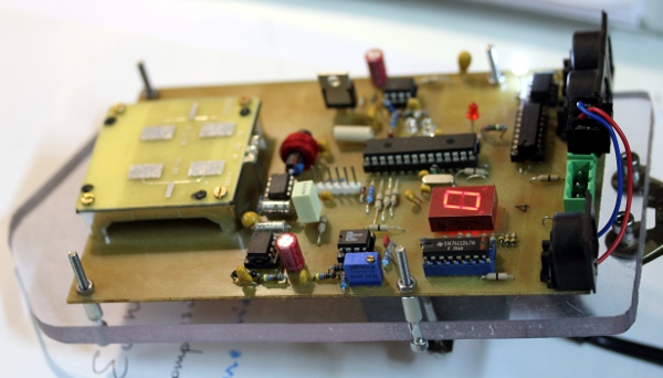
2. Radar 4:
The single sided hand drawn PCB for this circuit (200%) is:
There are no fundamental differences between the boards. On the Radar 4 board, provisions were made to add a single digit hex display, for ease of debugging and monitoring. Both boards measure 100 x 160 mm (Eurocard format) the radiating antenna -integrated on the board-, being located on the frontal side. The radiation angle of the antenna is 60 degrees.
Their operating frequency is specified at 10.587GHz. The emitted electromagnetic waves are reflected by reflective surfaces and if in movement, these will cause a Doppler shift between emitted and reflected signal. As to human bodies, the most reflective surface is the naked skin.
Doppler formula:
fd = 2 v fo / c
c = speed of light
fo = operational frequency
v = movement speed in line with the antenna expressed in m/s
fd = Doppler frequency
, after solving the device specific constants we get:
fd = 70 v
This holds for movements in line with the axis of the sensor. For other angles, the formula becomes:
fd = 70 v cos(a)
Where a is the angle between the movement and the axis of the sensor. The circuit is optimised for the movement velocity range between 2.6 cm/s and 5 m/s
When we sample the signals at 256 S/s, the highest detectable frequency would be 128Hz, conforming to the Nyquist theorem. So this limits the maximum detectable movement speed to:
v = 128Hz / 39 or ca. 3.2m/s.
So if we wanted to be capable to resolve movement with higher speeds, we would have to increase the sampling rate accordingly. Note however that moving human bodies rarely exceed speeds of 5 m/s. Therefore sampling rates much higher than 512 S/s do not lead to any gain in information particularly since the board used has pretty sharp low pass filters.
Signal amplitudes are inverse proportional to the square of the distance to the antenna and directly proportional to the size of the reflective surface of the moving body. The detection range for these devices is variable from 1 to 10 meters. Noise limits the range of the unit. Since we want the device to operate in real time, there is no way to resolve signals below or around the inherent noise level of the devices. The polar sensitivity, according to the datasheet, shows an opening angle of 60° in a conical shape.
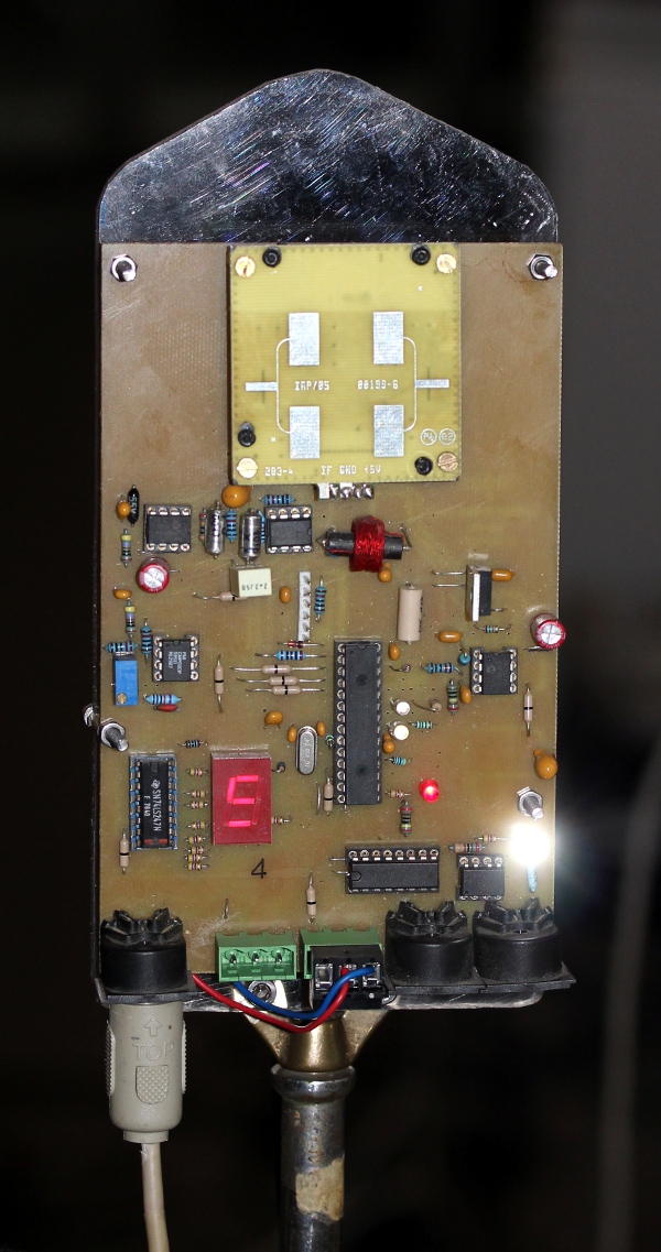
In august 2021, we made this board into a stand-alone sensor, mountable on a microphone stand, such that it can be used to steer our <Tubo> robot. Here is the source-code for Radar_4. The hex-dump, compiled and ready for programming into the PIC controller is here. Here are some picture of this radar module: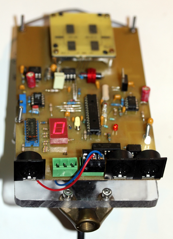
3. Radar 5:
Building further on the design of the radar 4 board, we also designed a version using a 24GHz sensor. This puts all Doppler frequencies more than an octave higher and thus the filters needed to be recalculated. Here we used a second order Sallen & Key filter with a cut-off frequency at 1.5kHz. This is the circuit:
For the radar sensor, different types can be used: RSM1650 as well as RSM1700, the difference between both is only the radiation pattern of the antenna. The RSM1650 has a horizontal opening angle of 80 degrees, and vertical 32 degrees. The RSM1700 has 70 degrees both horizontal and vertical.
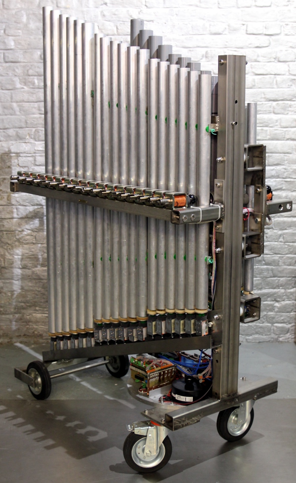
As we noted in earlier publications based on our research into microwave radar devices (1), the sensors used here can also be disturbed by ionising sources in their neighbourhood and range of sight. When using the 10 to 30GHz range, the effects of gasdischarge lights often made the use of the equipment problematic. So the use of this equipment together with CRT's, TV-sets, TL-light, mercury vapor bulbs, our own digital loudspeakers, welding equipment, sodium vapor bulbs within a range of 10 meters around the setup should be discouraged. At certain occasions we also noticed disturbencies caused by WiFi, Bluetooth devices and cellular phones. Another consideration to take into account is that all these devices do pickup acoustical and mechanical vibrations. Thus, if the sensor assembly is to be incorporated in a (vibrating) musical instrument or a moving robot you have to make sure the mounting provides in damping. Elastic suspensions work pretty well here.A few more systems operating on 24GHz were made: Radar6 found a permanent place in our <Kazumi> robot, an automated kazoo, finished in march 2023. Radar7, shown on the picture below, is meant to be used on the <Rumo> robot.
This robot likely will be equiped with two such radar boards.
Software:
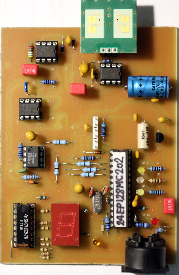
The software was developped for a 16 bit MIcrochip dsPIC controller, in this case, type 24EP128MC202. The code also runs on ds33 processors. Data acquisition is coded entirelly interrupt based, whereas the embedded composition code runs in a real time multitasker of our design. The Proton24 Basic compiler was used for software development and compilation, in tandem with MPLAB by Microchip.
An improvement relative to earlier designs of the software is that we implemented variable integration time in function of the detected speed of movement: as soon as a period is determined (this happens in the interrupt service routine (ISR) for the external interrupt, we calculate the sum of all values in the ADC databuffer for the duration of that single period. Thus each period measurement is coupled with a true amplitude value calculated over a full period. Further integration is than performed over a fixed number of data pairs. Thus the integration time becomes a continuous variable. This highly improved responsiveness of the interface.
Radar board 3 found its final destination in our <aeio> robot. It's firmware contains 5 embedded interactive compositions. Here is a link to the source code. Radar board 4, found an application in a stand-alone set up for the <Tubo> robot, presented at the SMAK museum september 2021. Radar 5, operating on 24GHz, found a place in our tiny <Steely> robot, an automated steeldrum finished in 2022. Radar 6 is in the <Kazumi> robot, finished in 2023. Radars 7 and 8 can be found in our <Rumo> robot.
Artistic applications
<Rodo>, a fully interactive musical robot (using radar boards 1 and 2)
<Aeio>, an interactive aeolian cello robot (using radar board 3)
A complete description of this robotic project can be found on the corresponding webpage for Aeio.
The <Tubo> robot, using Radar board 4:
The <Steely> robot, finished in 2022, using the 24GHz radar sensor:
Radar board detail:
In April 2023, we finished an automated kazoo, a robot named <Kazumi> and here we used the Radar6 board operating with a 24GHz sensor, to make it interactive and gesture controlled.
Radar7 and 8 are built into our large <Rumo> robot, finished in 2023.
The equipment is available for any competent composer wanting to develop a piece or performance using it. Since the use of the instruments requires software to be written, it is highly advisible to study our PIC based software and its functionality with regard to this sensing system. We can also accept commissions for dedicated radar boards.
Dr. Godfried-Willem Raes
Notes:
(1) This project is part of the ongoing research of the author in gesture controlled devices over the last 40 years. Earlier systems, based on Sonar, Radar, infrared pyrodetection and other technologies are fully described in "Gesture controlled virtual musical instrument" (1999) as well as in his doctoral dissertation 'An Invisible Instrument' (1993). Artistic productions and compositions using these interfaces and devices have been: <Standing Waves>, <Holosound>, <A Book of Moves>, <Virtual Jews Harp>, <Songbook>, <Slow Sham Rising>, <Gestrobo>, <Technofaustus> , <Namuda Studies>, etc.
(2) People interested in ordering a system as described here can take contact with the author.
Bibliographical references:
- BECKMANN, Petr & SPIZZICHINO, Andre "The Scattering of Electromagnetic Waves from Rough Surfaces", Pergamon Press, Oxford, 1963
MARSH, David "Radar reflects safer highways", in: EDN-Europe, p.21-29, 03/2003- Microwave Solutions Ltd. Datasheet for the MDU sensing devices.
- RAES, Godfried-Willem "Een onzichtbaar muziekinstrument" (Gent, 1993)
- RAES, Godfried-Willem "Gesture controlled virtual musical instrument" (Ghent, 1999)
- RAES, Godfried-Willem "Logos @ 50, het kloppend hart van de avant-garde muziek in Vlaanderen", ed. Kunstboek, Oostkamp 2018.
- RFbeam Microwave GmbH, 'Application Note AN-04', 18.08.2014
- SAMRASH Company "Users Manual for the BumbleBee", (05.2008) http://www.samraksh.com/support.html
- SINCLAIR, Ian Rorbertson., "Sensors and Transducers" (London, 1992) , ISBN 0 7506 0415 8
First published on the web: 03.05.2017 by dr.Godfried-Willem Raes
Last update:2023-06-12