Random spikes and pulses..
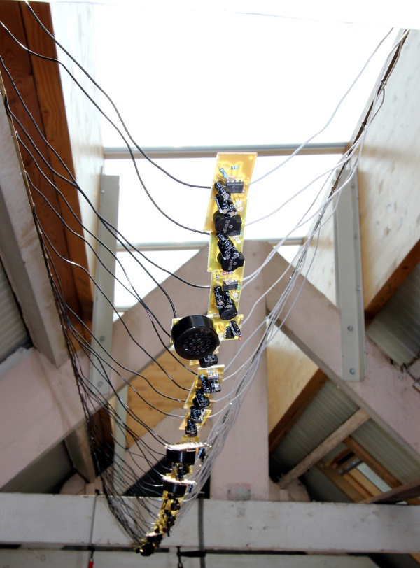
Our collaborator dr.Laura Maes at Logos Foundation got a commission for an audio art installation to be installed at Dartmouth College in 2017. Her idea was to have an entire ceiling filled with little circuits producing spikes and clicks powered from solar cells, placed outside. Designing simple circuits to produce pulses seemed pretty simple and our first idea was to use a simple UJT circuit, an oldie but still a valid option.
The UJT's are still on the market, at least at the time of this writing, (here is the datasheet for the 2N2646), but their price (ca. 4 Euro) is much higher than that of another classic, the infamous NE555 chip. Here is a practical circuit:
Five components only... The 555 chip at Farnell and at the time of writing was priced at only 20 eurocents if bought in quantities of at least a hundredth. So we decided to go for it, as we needed some 200 of these circuits working in parallel anyway.
However, the problem that raised was how to make a circuit producing randomly varying pulses... Evidently, in the analog domain, we would look for devices having a natural random behavior (such as noise diodes, or transistors configured to operate as such) or transducers for natural random phenomena. The first idea in this direction we came up with, was to use natural radioactivity and the Geiger-Mueller tube used for detecting and measuring it. Every time a particle (alfa) hits the tube,a discharge takes place and a pulse can be observed and made audible. The time between particle hits is random and only the probability of hits gets higher with higher radioactivity levels. It would have been a great idea, if it weren't for the price and complexity... Geiger-Mueller tubes need a pretty high voltage to work well and need a good high impedance amplifier stage behind them. Way too expensive for this project. The classic noise diode at the other hand, required a lot of analog (or digital) low pass filtering containing a lot of quite expensive capacitors in the 1 to 47uF range or, as an alternative, an expensive switched capacitor low pass filter (LTC1563 or similar) followed by a comparator or a Schmitt-trigger..
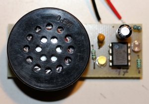
Thus we examined the old and proven 555 concept. Laura suggested to add a small LED on the PCB that would flash with each pulse generated. This brought us to the idea to use an LDR as a source of some degree of indeterminacy, by creating an optical and leaky coupling between the LED and the LDR. LDR's -soon they may become obsolete parts, as they contain some cadmium- are notoriously slow reacting devices... We figured out that if we have a cloud of some hundreths of these pulses, given they are not synchronised and due to component spread, the result would be pretty random. Moreover, the circuits being relatively close to each other, would certainly pick up some of each others light. The first prototype circuit was as straightforward as it could be:
The formulas to be used for component selection are:
f = 1 / (R1 + 2R2) .C1. ln(2)
duty cycle: ta / tb
ta = ln(2).(R1+R2).C
tb = ln(2).R2.C
T = ta + tb
It will be clear that reducing the value of R2 will make the pulses shorter. When the LDR is dark, the pulse frequency will be slowest. If cost is an issue, the 47n capacitor on pin 5 can be dropped at the detriment of some stability. The minimum voltage for this circuit to work is 4.5V. If the Cmos version of the 555 chip is used (7555), it would work from 2V on, but in that case a white LED cannot be used. On such low voltages it should be red and the current limiting resistor should be lowered to 47 Ohms. Obviously, sound level will go down a lot when lowering the voltage, even if an 8 Ohm speaker is used. The speaker we used for this first prototype is a tiny Visaton K16 (Art.nr 2816, www.visation.de). When a lot of these circuits are made to work and sound together, we obtain a nearly random result, as the oscillators are not synchronised and their LDR's show up quite a spread in resistance value.
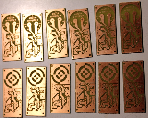
Here are some PCB versions (scale is 200%) we made for experimenting with component values and specifications:
Here are a bunch of etched and drilled prototype boards:
Although the circuit as shown performs quite well, Laura found the frequency under full light condition too high. So, we added a fixed resistor in series (82k) with the LDR and a parallel resistor (10M) as well, to limit the slowest pulse rates. Now the circuit became:
A new PCB to accomodate this circuit was drawn as well.
As cost was a major concern in this project, we tried to examine alternatives for the 16 mm 50 Ohm Visaton loudspeaker (ca. 4 Euro's a piece). Magnetic buzzers came up as they can be bought for less then 1 Euro. Their problem however is that they produce a definitly pitched sound. So, in order to make them produce pure spikes, the pulses generated by our circuit must be made so short that pitch becomes unnoticable. Hence the value for R2 in the circuit, taken as 150 Ohms. Something to watch out for: the output of the 555 chip is not short circuit protected! Make sure the current never exceeds 200mA. This is why we use a 50 Ohm speaker. If you want to try 8 Ohm loads, a capacitor in the 1uF to 4.7uF range can be placed in series with the speaker, or the LED can be placed in series with the speaker, thus saving even more on components:
Needless to say that we also considered solutions in the pure digital domain: we could design a circuit around an 8-pin Microchip PIC controller. Randomness is certainly easier to achieve, but costs will be quite a bit higher unless we could go to industrial quantities of say over 5000 pieces...
Evaluation table for the different prototypes build up and tested:
Nr. board C1 Rs Rp R2 Rl /Cl transducer remarks 1 breadboard - 50 Ohm - 50mm speaker no LDR 2 PCB V1 1uF 1M - 10k - 50 Ohm Visaton K16 50 Ohm no LDR - soft 3 PCB V1 1uF 1M - 10k Piezo disk 20mm too silent - needs resonator 4 PCB V1 1uF - 1.8M 10k KPX-G1205B 5V/30mA 3.1kHz LDR - too fast -->musicbox 5 PCB V1 10uF - 10M 150 Multicomp MCKPI-G2210L-3672 LDR - high pitched 6 08.02.2017 10u 82k - 150 - KPX-G1212UB 12V/30mA 2.3kHz ok 7 07.02.2017 10u 82k - 150 82 KPMB-3008E 8 Ohm, 150mW ok - non pitched 8 08.02.2017 10u 82k - 92 - KPX-G1205B 5V/30mA 3.1kHz ok 9 08.02.2017 10u 82k - 102 - KPX-G0905B 5V 2.,7kHz ok 10 08.02.2017 10u 82k - 92 - KPX-G1205A 5V/30mA 2.3kHz ok 11 07.02.2017 10u 82k - 76 - 50 Ohm Visaton K16 50 Ohm ok soft 12 07.02.2017 10u 82k - 75 Piezo disk 20mm too silent 13 07.02.2017 10u 82k - 82 47 ABT408-RC magnetic single pulse ok - non pitched 14 07.02.2017 10u 82k - 68 2u2 ABT408-RC magnetic single pulse ok ++ 15 08/02.2017 10u 91k - 82 - KPX-G1205A 5V/30mA 2.3kHz ok beetje lager dan nr.10 16 08.02.2017 10u 91k - 76 KPX-G1205A 5V/30mA 2.3kHz ok 17 14.02.2017 10u 82k - 150 82+LED KPMB-3008E 8 Ohm,150mW too soft 18 13.02.2017 10u 91k 68 1u5 ABT408-RC magnetic single pulse 19 pcb's made 19 08.02.2017 10u 82k - 82 2u2 EKULIT LSF15WS 112 15mm ok dry click 20 13.02.2017 10u 82k - 75 1u5 ABT408-RC ok Here is a picture of a handfull of assembled test boards:
After some experimenting, we concluded that we could save yet another component: the 10M resistor, in parallel with the LDR. The penalty is that the pulses will stop completely when it is completely dark. Seen the application, this is rather an advantage.
Here is a picture of prototypes 7 to 12:
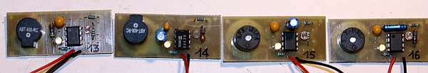
For the prototype 13 and 14 we used a non-self oscillating magnetic sounder (ABT408-RC). This required some changes in the circuit as the sounder is designed for operation on 3Vpp maximum. In prototype 13 we used a series resistor (47 Ohm) at the detriment of sound volume. Prototype 14 uses a capacitor on the output pin in series with the sounder, with much better and louder results. Here is the circuit:
Here is a picture of prototype nr. 13 to 16:
Prototypes 17 and 18 came out to look like this:
.Prototype 19 uses an 8 Ohm, 0.8W speaker (Ekulit LSF-15), as small as 15 mm in diameter and therewith even 1 mm smaller than the Visaton type. They are priced at 2.09 Euro a piece at Conrad.
Clearly the PCB's could become quite a bit smaller if we would have designed them using SMD components only. The prospect of handsoldering 200 boards with SMD's however was prohibiting.
It goes without saying that all these circuits can be used for a wealth of different purposes. If the timing capacitor is taken a factor 100 to 1000 smaller, they become audio oscillators. With the LDR it becomes very easy to bulld an optical theremin or a cracklebox, if you use your fingers -an even cheaper component- instead of the LDR...
Laura Maes 'Spikes' installatieprojekt (15.08.2017 - 10.12.2017 Darthmouth College, Hanover NH, USA)
Overzicht van de technische opbouw:
Er zijn vijf kringen die elk via een eigen zonnepaneel worden gevoed. De 7815 spanningsstabilisatoren hebben als belangrijkste funktie het begrenzen van de maximale spanning voor de puls-schakelingen tot 15V, overeenkomstig de maximale werkspanning voor de 555-chips. De zonnepanelen kunnen immers een spanning afleveren tot ca. 22 V bij optimale blootstelling aan zonlicht. Hier is de datasheet voor de CBSPGF_30 panelen. Hier is de werkingskurve voor de spanningsafgifte in funktie van lichtsterkte. Wanneer donkerte invalt, zakt de spanning van de zonnepanelen tot 0V. Zolang de spanning groter blijft dan 4.5V zullen de aangesloten schakelingen blijven werken en uitsluitend het geluidsvolume zal afnemen.
Hier is een foto van de eerste reeks van ca.170 printjes:
De uiteindelijke schakeling voor de voeding kwam eruit te zien alsvolgt:
Circuit for the 5 power supply PCB's:
Printed circuit lay out:
Door de parallel-schakeling van drie 7815 regulators, is de maximale leverbare stroom 3 A. De 1 Ohm weerstanden moeten 1W types zijn. De uitgangsspanning is maximaal 14.4V. De zonnepanelen zelf, leveren slechts 5 Watt (of 300mA), voldoende voor het voeden van 40 printjes, aangezien die per stuk een stroom trekken <= 7mA (gemeten gemiddelde waarde). De overdimensionering van de voedingsschakeling is hierdoor ingegeven dat ze ook moet blijven werken bij hoge temperaturen, aangezien de boards gemonteerd worden op de achterzijde van de zonnepanelen, waar de temperatuur kan oplopen tot 85 graden.
Praktische problemen...
Het eerste groot obstakel dat we ontmoeten in een testopstelling (foto hierboven) met een vijftigtal spike printjes aangesloten op een zonnepaneel was dat de oscillators gingen synchroniseren, wat gezien de toepassing helemaal niet de bedoeling was. Het plaatsen van een 'dikke' elektrolytische kondensator over de uitgang van de voedingsschakeling (10000uF) loste het probleem niet onmiddellijk op. Zonnepanelen blijken niet goed overweg te kunnen met puls-belastingen. Die voor de hand liggende oplossing met een bufferkondensator parallel met de uitgang van het paneel, zoals o.m. berekend en gesuggereerd door Chris Glaser in 'Easy solar-panel maximum-power-point tracking for pulsed-load applications' bleek absoluut niet afdoende. Wellicht hadden we de 10uF kondensator op de printjes veel groter moeten nemen en een serieweerstandje toepassen (100 Ohm tot 1 kOhm bvb.) in de positieve voedingslijn. Het probleem vindt zijn oorsprong in de grote stroomstoot die de 555 chip veroorzaakt bij het omschakelen van de uitgang. Het probleem is analoog aan het verschijnsel dat optreedt wanneer we mechanische uurwerken of zelfs metronomen op een gemeenschappelijke plank zetten: ook hier treedt synchronisatie op, ook al stellen we de metronomen in op lichtjes verschillende tempi. Een proefopstelling gevoed door onze laboratorium voeding vertoont dit synchronisatie gedrag niet, wat erop wijst dat de inwendige weerstand van de zonnepanelen en onze voedingsschakeling te hoog is. Nagerekend is die immers 56 Ohm. Ook wanneer we de stroombegrenzing in onze lab-voeding op een heel lage stroom instellen, wat dus de spanning onstabiel maakt, kregen we de schakelingetjes niet aan het synchroniseren. Zelfs de plaatsing van een 47mF elektrolytische kondensator over de voedingslijnen bleek dit niet te kunnen remedieren. Een betere ontkoppeling van de spike printjes onderling bleek uiteindelijk soelaas te kunnen bieden:
Deze remedie gaat echter wel ten koste van een flink stuk geluidsterkte omdat de voedingsspanning nu wordt gereduceerd. Idealiter hadden we veel krachtiger zonnepanelen moeten gebruiken...
Dit <Spikes> projekt werd in 2018 aangekocht door de opdrachtgever. Het is nu een permanente installatie geworden die deel uitmaakt van de kunstverzameling van Darthmouth College. In 2022 kreeg het een vaste plaats in het museum.
https://hoodmuseum.dartmouth.edu/explore/publications/resonant-spaces-sound-art-dartmouth?page=13&fbclid=IwAR2c6ASc-J3pHxyH8zxxe1QgkNz6XCfwR9TdeQvE8tvbsXWpAZRLuWa2MJg
Optical theremin birdcalls:
We re-used prototypes nr.2 and 11 to make some birdcalls controlled by light. Following component values were used:
C1 R2 R1 2 PCB V1 4n7 0 - 18k - 50 Ohm Visaton K16 50 Ohm Large LDR 11 07.02.2017 3n9 0 - 18k - 50 Ohm Visaton K16 50 Ohm Small LDR This is the modified circuit drawing:
These little circuits, powered from a 9V square battery, found applications in Lieve De Pelsmaeker's 'Sonomobielen' (ca. 1972), in Moniek Darge's musicboxes as well as in some glass sculptures produced at Ghent Glas. Original prototypes nr.3 and nr.12 modified for use in music boxes.
Godfried-Willem Raes
Ghent, February 8th- August 25th, 2017
References and data sheets:
- NE555
- Advanced Photonix NSL19M51 : LDR datasheet
- http://sound.whsites.net/articles/555-timer.htm
- White LED: Multicomp OVL-3321
- Datasheet UJT Multicomp
- Visaton K16-50 Ohm: www.visation.de
- Multicomp sounder MC ABT-408-RC
- KPX-G1205B-K6339 Datasheet
- Chris Glaser 'Easy solar-panel maximum-power-point tracking for pulsed-load applications'
- Ting-Hsiang Chuang "Distributed Synchronization of Electronic Fireflies" (2004)
- Raes, Godfried-Willem "Logos @ 50" (2018)
to index-page Godfried-Willem Raes 
08.02.2017: First designs and experiments.
09.02.2017: some test PCB's made.
24.04.2017: 3 more wafers of 22 PCB's etched. Laura soldering works.
25.04.2017: gwr soldering works on some more prototype boards. 20 production boards finished.
26.04.2017: gwr soldering:45 production boards finished.
27.04.2017: Drilling works Mattias and Laura. Solder works Mattias and gwr: 100 production boards finished, so we are halfway!
28.04.2017: 40 more PCB's drilled and cut.
29.04.2017: We are at 125 finished production boards.
30.04.2017: 152 boards finished... Tomorrow, 3 more boards of 22 units to be etched and produced.
01.05.2017: 66 boards etched.
04.05.2017: some more drilling by Mattias. gwr soldering. 165 boards finished now.
06.05.2017: 175 boards finished.
08.05.2017: More drilling work by Laura Maes. PCB design for the power supply boards.
09.05.2017: 187 boards finished. Etching of the 5 power supply boards. 1 Power supply board soldered and tested.
10.05.2017: 199 spike boards finished. Power supply boards drilled.
11.05.2017: 5 power supply boards soldered and tested. Spike board nr.200 finished.
06.08.2017: Test setup in our lodge using 50 spike boards connected to a single solar panel.
07.08.2017: Encountering a major problem: the boards tend to synchronize.
08-09.08.2017: Solving the synchronisation problems.
15.08-25.08.2017: Mounting of the <Spikes> project by Laura Maes at Dartmouth College (Hanover, N.H., USA).
oktober 2022: definitieve aankoop en vaste plaatsing van het Spikes projekt in Dartmouth College. https://hoodmuseum.dartmouth.edu/explore/publications/resonant-spaces-sound-art-dartmouth?page=13&fbclid=IwAR2c6ASc-J3pHxyH8zxxe1QgkNz6XCfwR9TdeQvE8tvbsXWpAZRLuWa2MJg