A 5-channel mixer and preamplifier for piezo contact microphones
Piezo disks are used almost universally by experimenting musicians all over the world. They have been around since the mid seventies of last century. (1). Generally people connect them to unbalanced microphone inputs of power amplifiers. The resulting sound is more often than not, harsh and metallic. Here we propose a much better solution, based on a good understanding of the nature of piezoelectric transducers. A piezo disk basically is and behaves as a capacitor, generating a voltage when exposed to vibration. As a consequence, the impedance is a function of excitation frequency and can be considered infinite when no signal is generated. Such a generator makes a very bad source for a regular microphone input.
Here is a much better battery operated solution for a preamplifier for piezo disks:
The first op-amp in this circuit is a current amplifier. Basically the piezo disk connects to the inverting input and thus sees a zero impedance. It is virtually shorted. The current produced by the disk is amplified by a factor Av = Xf / Xi, wherein Xf = 1 / (2.Pi,f.Cf) and Xi = 1 / (2.Pi.f. Ci). Substitution then leads to the conclusion Av = Cp /Cf , where Cp corresponds to the capacitance of the disk, generally in the order of 10 nF to 24 nF. (see table below). Note that Av is inherently independent of frequency here, thus we avoid the sharp and metallic sound obtained when using a non-inverting opamp configuration. The 100 MOhm resistor limits DC gain and prevents oscillation. It determines the low frequency roll-off. The higher this resistor, the lower the cut-off frequency. Resistors with such high values are not common. (2) It you are in trouble tracing them, you can also use common 10 MOhm resistors. The 1N4002 diode (about any type will do) serves as polarity reversal protection, no luxury as we noticed many users try connecting a battery in its holder until it fits... The TLO71 opamp specified here, operates at 1V below its minimum Vcc-Vss range, yet it works. It can be exchanged for any low noise low voltage type. We designed this circuit some 35 years ago, at a time low voltage op amps were not readily available, the standard being -15V and +15V.
The diode circuit following the first amplifier stage, makes a limiter. If the signal on the input exceeds the diode forward voltage drop (ca. 250 mV for germanium diodes, 600 mV for silicon types),the excess signal flows through the capacitor and high frequencies get attenuated more than low frequencies. With the 1k series resistor and the 47nF capacitor as drawn, the -6 dB point is at 3.4 kHz. Thus it makes a simple soft clipper/compressor. The response time is determined by the RC time for the 47 nF and 2.2 M Ohm conbination, so in this case 100 ms. It is the kind of circuit that once was very popular amongst short-wave radio amateurs for listening to Morse code broadcasts. The germanium diodes (AA119, OA91 etc.) nowadays may be hard to find. (3) They can be replaced with BAT86 Shottky diodes (Vf = 260mV). Do not use regular silicon diodes, as at clipping, they will cause the second op amp to saturate. This is because the peak voltage of the signal with regular silicon diodes equals 1.2 Vpp. As the second op amp has a gain of 10, the output should become 12 Vpp, a value that could only be reached when the power supply is higher than 12 V. If you find the operation of the soft limiter still sounding too harsh for your application, increase the value of the 47nF capacitors. If you want to increase the attenuation, increase the value of the 1k resistor connected to the output pin 6 of the first op-amp.
The final opamp, just mixes and amplifies the signal further to a strong and hefty line level. If long cables are to be used, select an AD820 opamp rather than a TLO71.
As in some applications such as sound sculptures and audio art, often the signals of more than a single piezodisk are to be combined, a mixer circuit comes in handy. Here is a small PCB for a simple but effective 6-channel mixer: (reduce to 50% for printing the film).Here is the corresponding circuit:
In the following and final project design, we combined these ideas to make a 5 channel piezo disk mixer, with individual channel volume controls as well as a master volume control. Here is the circuit:
Note that metal film resistors should be used throughout for lowest possible noise. The mixer stage can make use of an TLO71. AD820 (datasheet) or TLC071 (datasheet) opamp, but if the circuit is to drive long cables, the AD820 makes a better choice, as it can drive quite large capacitive loads without stability problems. The headroom and maximum output voltage swing of this circuit can be improved by raising the power supply voltage. Make sure not to exceed the absolute maximum ratings for the opamps used. If different types of opamps are used in this circuit it is mandatory to go for JFET input low noise types, preferably with output swings up to the supply voltage. Also, make sure to check the minimum Vcc voltage for the part. If specified at higher than 9V, consider using a 12V or higher voltage battery pack. Our favorite long line driver op amp, the rock stable LF356, unfortunately requires a 30V power supply and cannot be used, unless we redesign the circuit with a proper -15V - 0 - +15V power supply. The AD820 performs very well here, but it's a rather expensive component.
If you want to check it out and build it yourself, here is a single sided PCB design (at 200%):
In quite many experimental instrument building and soundsculpture applications, it is not required to build the circuit with input volume control portentiometers. If the circuit is to be build into such a project, the potmeters can be replaced by fixed resistors. Determine their value by making a good sounding balance, measure the resistance value of the potmeters at that setting and replace them with fixed values. Not only this improves lifetime of the circuit, but also it entails quite a saving on building costs. Renounce the tempting idea to replace the potmeters with trimpots, as these components are amongst the least reliable of all. Of course this also applies to the output volume control. Generally the only thing you have to make sure, is that the output is a nominal 0dB level, or whatever level you decide to stick to. Remind you: 0dB means 0.775 Vrms, or 2.2 Vpp.
If you want to etch the PCB, save the gif image on your computer and laser-print it on transparent foil reduced to 50% in size. The circuit fits a standard Eurocard PCB (100 mm x 160 mm). Assembled and tested circuits, using top quality low noise components and potmeters can also be bought from the Logos Foundation for approximately 450 Euro's. Inquire by email to mattias@logosfoundation.org. Silicon mount piezodisks can be obtained as well.
As the value of the feedback capacitor in the pre-amp circuit depends on the capacity of the piezo disks connected, we measured some different types. This may be usefull for users not equiped with a capacitance meter or a detailed data sheet for the product. As you will notice, the capacity is not always a function of size, as it also depends on the thickness of the piezo ceramic layer. Here are the results of our measurements:
disk diameter / thickness measured capacity practical value for Cf source remarks 12 mm 0.22 mm 7.8 nF 820 pF Farnell nr.2433032 fres= 9.5kHz 15 mm 0.22 mm 9.35 nF 1000 pF Murata
Farnell nr.2443195
fres = 6 kHz 15 mm 14.6 nF 1500 pF 15 mm 0.13 mm 34 nF 3300 pF Multicomp
Farnell nr. 2667639
fres = 4 kHz 20 mm 0.2 mm 10 nF 1000 pF Murata
Farnell nr. 1192520
fres=6.3 kHz
wired
20 mm 0.22 mm 20 nF 2200 pF Murata
Farnell nr. 2443197
20 mm 0.4 mm 6 nF 680 pF Multicomp
Farnell nr. 2433033
fres = 6.4 kHz 27 mm 0.52 20 nF 2200 pF Multicomp
Farnell nr. 1675548 (wired)
Farnell nr. 2443198 (unwired)
fres = 4.2 kHz 28 mm 23.8 nF 2200 pF Hungary 30 mm 26.1 nF 2700 pF Hungary 35 mm 0.3 mm 30 nF 3300 pF Murata
Farnell nr. 1192552
fres = 2.8 kHz 35 mm 0.53 mm 22.9 nF 2200 pF Murata
Farnell nr.2443199
fres = 2.8 kHz 35 mm 0.51 mm 37 nF 3300 pF Multicomp
Farnell nr.2433034 (unwired)
Farnell nr.2433035 (wired)
fres = 2.8kHz 50 mm 24.8 nF 2700 pF Conrad
order nr. 541-022-08
type FT-50T 6 mm x 14 mm square 4.7 nF 470 pF Hungary If you have no idea what kind of piezo will be connected to the circuit, it is a good compromise to go for a 1.5 nF value.
Here is a picture of the first prototype of the complete circuit:
Four of the five potentiometers on the inputs are missing, as we didn't have them in stock at the time we took the picture. The output volume control potentiometer is missing as well. There are some slight differences between the PCB published above and this prototype, as we changed and optimised placement of components a bit in the last version of the PCB. Here is a picture of the third prototype:
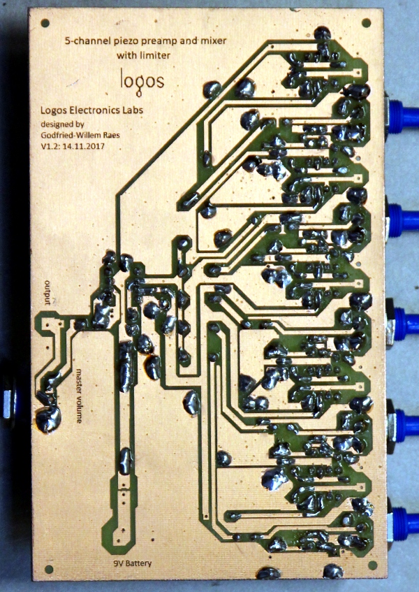
And here is a picture of the soldered copper side:
For people preferring a version using a dual bipolar power supply (or two 9V batteries), we worked out a circuit as well. Note that this version shows a clear saving on relatively expensive capacitors. Another advantage of this version is that the inputs for the piezo disk are at ground level.
Thus in this case, shorting an input to ground, will not cause a strong plop-pulse on the output.
Current consumption of the circuit is ca. 10 mA, using six AD820 op-amps, so a regular 9 V alkaline battery (the capacity is ca. 550 mAh) can be used with an expected lifetime of ca. 40 hours. For the dual supply version, this becomes 80 hours. Note that the TLO71 version draws about twice as much current as compared to the AD820.
In the early days of live electronics, one of the devices seen all over setups was the infamous Eagle mixer, a very small 4 input line level mono mixer. The internal circuitry was of an utmost simplicity: a passive mixer using four rotary potentiometers followed by a single transistor (a Japanese PNP germanium type...) emitter follower. This mixer was very cheap and its performance pretty poor as well. It produced a lot of noise. However it was in use amongst hundreths of musicians and populated as many stages. With some nostalgia, we remade such a 4-input mixer, here in a version for 4 piezo disks, in the same form factor. The PCB would even fit in the old housing, but if anyone considers reusing an old cabinet, please replace all potentiometers as the original types are of an extremely lousy quality. Here is our PCB for such a nostalgia 'Eagle' mixer:

Godfried-Willem Raes
Ghent, November 8th to 12th, 2017
Notes:
(1) A historical source on piezo-electrics is: Ed. Palmans, 'Piezo-electriciteit'. ed. P.H.Brans, Antwerpen,1942. A bit more recent: J.W.Waanders 'Piezoelectric Ceramics', ed. Philips Components, Eindhoven 1991. Early adopters of piezo disks in experimental musics were Richard Lerman, Alvin Lucier, Takehisa Kosugi, David Behrman, Hugh Davies, Hans Karsten Raecke, Daniel Senn, Michel Waisvisz, Paul Panhuysen, Dick Raaijmakers, Dan Senn, Pauline Oliveros, Wolf Dieter Truestedt and many others.
(2) 100 MOhm resistors are a.o. made by Ohmite and can be ordered from Farnell (ord. nr.2664957). They are a lot more expensive than 'regular' values.
(3) Not a single germanium diode can be found in Farnell's otherwise extensive catalogue. AA119 diodes are popular in music circles and go for prices in the order of 4 Euro's a piece on Ebay. Matched pairs go even higher prices. The reason why these diodes are so much looked after is that their forward voltage drop is very dependent on the current flowing through the diode. (cfr. data sheet). Hence its application in quite many simple audio compressor circuits. This particular circuit has been around at least since the early seventies:
We have no clue as to the original author. The trim potentiometer is used to adjust the decay time of the limiter-compressor. Note that the input impedance is very low and thus the circuit must be driven by an amplifier output. The output also requires buffering, as it has a high impedance. Worked out with this in mind, the practical circuit becomes:
We also designed a small PCB for this circuit, here at scale 200% :
At Logos Foundation we still have quite some new AA119 matched paired diodes in stock. If you want to buy some, we charge 3 euro's a piece. They must be bought in multiples of two. Order by email.
Due to the lack of specialists in the advisory boards, Logos Foundation lost its structural funding for the period 2017-2021. If you like our designs, please support us with a donation!
Stichting Logos
Kongostraat 35
9000 GENT, (Belgium)
Bank account: BE98 0000 4890 7093
to index-page Godfried-Willem Raes
Research into legacy electronics funded in part by the Orpheus Institute. This article is a preliminary version of an extensive publication on historical performance practice involving live electronics we are preparing for the Orpheus Institute (HIPEX project).

last update of this page: 16.11.2017 by the author.