A reminder for comparator design
The Schmitt trigger:
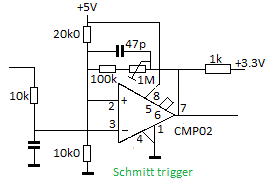
This is a practical circuit for unipolar signals centered around 1.65V:
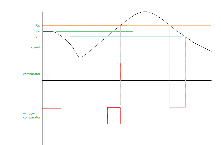
It converts an analog input signal to a series of pulses following the frequency of the input signal. These pulses can be fed to a frequency counter or a timer to measure the period of the signal.
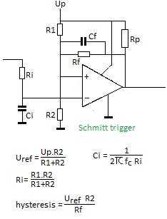
The output will follow the frequency of the input signal. Here is the principal circuit with the relevant formulas for the dimensioning:
Rp in this circuit is generally 1k to 4k7 and only has to match the input requirements of the following circuits. Ci is only required if there is a need for an input low pass filter. Cf is a speed-up capacitor to avoid high frequency glitches. The value depends on Rf and is generally in the order of 4.7pF to 47pF. If you drop the positive feedback network alltogether, the comparator works with the smallest possible hystereris but you risk a glitchy behaviour.
The window comparator:
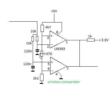
This is a practical circuit for unipolar input signals centered around 1.65V:
Note that the output frequency here will be twice the input frequency. The 470 Ohm trimpot allows adjustment of the window size. It should be adjusted to a value slightly above the noise level of the input signal.
Comparison of input/output behavior of both circuits:
Our favorite comparator chip has always been the CMP02. However, nowadays it has become an obsolete part... It can be replaced by the LM311 (or LM393 for a dual) , but that chip can give you headaches at times as it is a lot more unreliable and glitchy.
Godfried-Willem Raes
Ghent, april 16th 2017
to index-page Godfried-Willem Raes 


