A simple solution for a high voltage 500 Watt bench power supply
In the many years that we have been involved in the design and construction of musical robots, we must have blown up at least some twenty factory made laboratory power supplies. Not that we exceeded their ratings (in theory they ought to be well protected against that...), but because none of them were capable of dealing with fast switching load conditions or driving heavily inductive loads. Such loads and operating conditions however are normal modes of operation in robots, where all mechanical action is achieved by switching solenoids and/or motors. The culprit in commercial designs seems to be the way the current protection circuitry works.
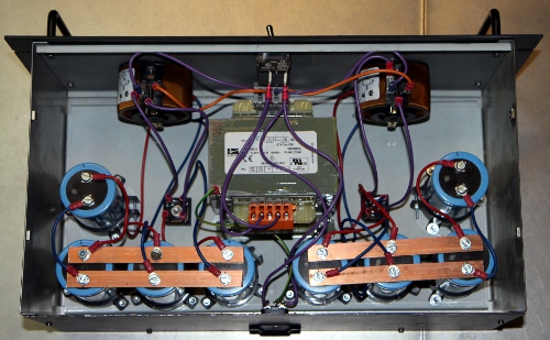
Hence we felt an urgent need to design a variable voltage power supply capable to withstand high surges and with a voltage range quite a bit higher than what's commercially available (mostly 0-30V). The most evident solution seemed to be to make use of a variable rotary transformer (a variac) rather than a conventional linear analog circuit to control the output voltage. As such that would be a very dangerous solution, taking into account that variable transformers are basically auto-transformers providing no insulation at all from the mains power. Hence the use of an isolation transformer to drive the variable transformers in our simple design for a dual voltage bench supply. We used two variacs rated for 120V. The data sheet for these transformers can be retrieved via this link. These transformers can be obtained from Farnell. The outputs can be switched in series with the midpoint grounded with a panel mount toggle switch. There is no provision for voltage stabilization. An extra advantage of this utmost simple design is that is has -in contrast to most commercial designs - no noisy fans, a major source of nuisance when working on musical instruments.
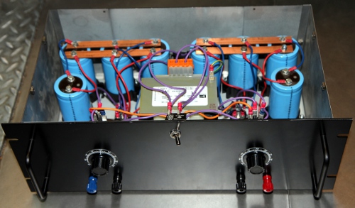
We mounted two analog voltmeters on the front panel but left out the usual current meters. The fuses (automatic resetable types) are mounted on the front panel as well and can be taken out for ease of current measurement using just about any external meter with a suitable range.
If parallel operation is required, make sure to first adjust both output voltages to the same value before paralleling the outputs. Also, the ser/sep switch must be in the sep position.
This is how the lab supply looks mounted in a 19" rack enclosure:
An easy way to implement voltage regulation in this circuit would be to have potentiometers mounted on the shafts of the variacs and connect these such as to set the base current of a couple of sturdy pass transistors or power MOSFETS. However, for the purpose of switching heavily inductive loads, including stepping motors, stabilization of output voltage is rarely required.
This bench tool has helped us also a lot in servicing and testing old and legacy vacuum tube equipment, as it easily meets the anode voltage requirements for such circuitry.
Godfried-Willem Raes
Ghent, august 9th 2014
to index-page Godfried-Willem Raes